
Specify how the probed points are displayed when a machine-generated results file is viewed in Drive or PowerInspect.
- Click File tab > Options > Application Options > Probing > Reporting.
- Use the Reporting page of the Options dialog to specify:
- The Proximity criteria around the stylus-tip, used to project the confetti of probed points onto the nominal CAD surfaces.
- How many decimal places are displayed for different dimensions.
- The label prefix for probed surface points.
- The size of confetti drawn on the model.
Proximity criteria
The Proximity criteria specifies a search distance measured from the surface of the stylus tip, which determines the maximum distance a probed surface point can be from the nominal CAD surface. If a CAD surface is not found within this region, the point is not recorded or displayed as confetti on the model.
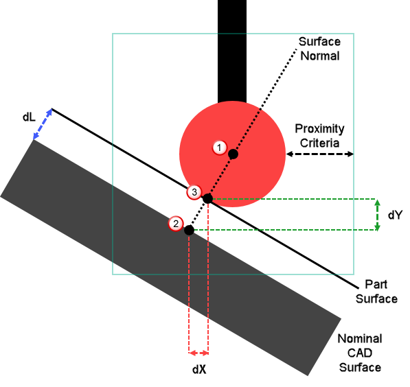
 The centre of the stylus tip. The magnitude of the Proximity criteria is measured from the surface of the stylus tip, and so is independent of the Stylus radius.
 The probed point displayed on the model as confetti. It is the nearest nominal point on the CAD surface within the boundary of the radial search. It is used to calculate the surface normal.
 The contact point on the part surface. This is found by projecting the stylus radius along the surface normal. This is used to calculate the deviations (dL ,
dX ,
dY, and
dZ) between the model surface and the part surface.
The contact point on the part surface. This is found by projecting the stylus radius along the surface normal. This is used to calculate the deviations (dL ,
dX ,
dY, and
dZ) between the model surface and the part surface.