
Use this dialog to choose how to apply Power Features.
- Power Features — Lists the Power Features of the source components. This column displays:
- The feature icon.
- For Hole features, the hole use. For example, Ejector pin clearance.
- For other features, the feature name.
Note: Position the cursor over the hole use to display the Power Feature solid name.Select a Power Feature from the list to highlight the row in the dialog, and the target component in the graphics window. Instrumentation is added to the Power Feature in the graphics window.
- Apply to — Each Power Feature contains a rule specifying how it is applied. These rules are based on the order in which the source component intersects with target components. For example, a screw (source component) will apply a counterbored clearance hole to the
First
plate (target component) it intersects with.
Each source component has a direction vector used to order these intersections, displayed as a blue arrow. You can modify this direction using the Modify Direction button on the Set Advanced Property for Power Features dialog. The First intersection is the nearest point on the source component along this direction, the Last intersection is the furthest point.
For a given set of intersections between the source and target components, this column shows how the Power Features would be applied. These options allow you to be specific about whether a Power Feature is copied to a particular target component, based on the intersection order of the target components. The options that may appear in the column are explained in the following table:
|
Apply to |
Action |
|
|
Copy feature onto all components. |
|
|
Copy feature onto all components except the first one. |
|
|
Copy on all target component except first and last |
|
|
Copy feature onto all components except the last one. |
|
|
Copy feature onto all components except the nth one. For example, if Number is 3, the feature will be copied onto all components except the 3rd. |
|
|
Copy feature onto the first component only. |
|
|
Copy feature onto the first and the last component. |
|
|
Copy feature onto the first and the second component only. |
|
|
Copy feature onto the last component only. |
|
|
Copy feature onto the last and the last but one component only. |
|
|
Copy feature onto the nth component only. For example if Number is 3, the feature will be copied onto the 3rd component only. |


 — Each target component that intersects with the source component is shown as a column on the
Power Features Summary dialog. The column order is determined by the order in which the target components intersect the selected source components. Click the
Target Components
— Each target component that intersects with the source component is shown as a column on the
Power Features Summary dialog. The column order is determined by the order in which the target components intersect the selected source components. Click the
Target Components

 buttons to change the intersection order.
Select a target column, or an option in the target column, to highlight the column or cell in the summary. The target is also highlighted in the graphics window, and instrumentation is added to the relevant Power Features for that target. Select (
 ) or deselect (
 )whether the feature is applied.
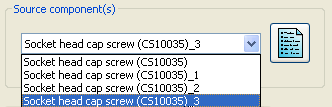
- Source Components — Select a source component from the drop-down list. If there are four bolts, the drop-down list contains four options. When you have chosen a source component, you can select the options for each Power Feature in the table for that component.
 — Select this option to set all options back to the default, as indicated by the source and target components in the assembly. If you have reordered the target components in the dialog, the rules are applied in this order.
Note: If the Power Features Summary dialog is activated from the Generate Power Features dialog, only the selected source components are shown in the Select source component dialog.
— Select this option to set all options back to the default, as indicated by the source and target components in the assembly. If you have reordered the target components in the dialog, the rules are applied in this order.
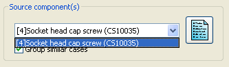
Note: If the Power Features Summary dialog is activated from the Generate Power Features dialog, only the selected source components are shown in the Select source component dialog.- Group similar cases — Select this option to group similar source components. Multiple components can then be modified by changing just one.
The example shows four identical components:
- Open Power Feature Summary dialog. The Source Components drop-down list contains all four components:
- Select Group similar cases. The Source Component drop-down list contains a single item.
- Deselect the Countersunk option in the Power Feature Summary dialog. The change is applied to all the components in the group.
- Open Power Feature Summary dialog. The Source Components drop-down list contains all four components:
- Target Components - The buttons in this section are highlighted when a target intersection column is selected:

Click the buttons to change the order that the target components intersect with the selected source components:
-
- The intersections are re-ordered and the current selection is moved earlier in the order. On the dialog, the current target is moved one column to the left.
-
- The intersections are re-ordered and the current selection is moved later in the order. On the dialog, the current target is moved one column to the right. Clicking this button sets the target intersection to be the same as the previous intersection.
-
 - Add the selected component as a target. The target is always added as the last intersection. You can the change the intersection order of this component and define how the Power Features are applied. This button is disabled if the selected component is already a target.
-
 - Remove the selected target. The component is removed from the intersection order and Power Features are not applied to this component.
-
You can make the target intersection the same as the previous (or next) intersection by using the following buttons:
-
 - Sets the target intersection to be the same as the previous intersection. The following example has three target intersection columns and illustrates how this option works:
- Select column
2:
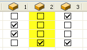
- Click
. The target intersection columns are updated; there are now two first intersections.
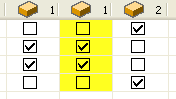
 — Sets the later target intersection to be the same as the current intersection.
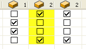
The following example has three target intersection columns and illustrates how this option works:
- Select column
2:
- Click
. The target intersection columns are updated; there are now two second intersections:
 — Resets the target column order to the default and applies the default intersection rules.
- OK — Saves your changes and closes the dialog. The options are applied and the Power Features are updated. If you opened the Power Features Summary dialog by clicking the Summary button on the Generate Power Features dialog, this dialog is also closed.