
 Geometry Editor
Scene > Geometry Editor or Scenegraph > Edit > Geometry > Tessellate Surfaces
The Geometry Editor contains functions for modifying scene geometry. Use it to adjust/flip normals and re-tessellate NURBS surfaces.
For using the Geometry Editor, see Working with Geometry.
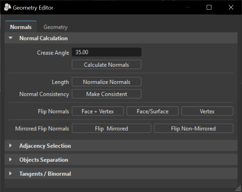
Normals Tab
These parameters affect the normals of the selected geometry.
Normal Calculations
Crease Angle - Determines the hardness of the shading between geometry edges. A lower value gives a harder look to the edges. While values around the default of 35 degrees give a smoother appearance.
Length - Normalizes the normal vector lengths in the geometry to a value of one.
Normal Consistency - Removes the inconsistencies with surface normals that can occur when importing geometry; some normals point inside and others outside (the Vertex/Face Normal Rendering Mode helps to identify affected objects). This option sets all normals so they are pointing on the same side of the surface geometry.
Flip Normals - Polygons got a font-face and a back-face; the face normal is located centered and in right angle to the font-face. For Ambient occlusion calculation it is required to have polygons turned to the right direction. Otherwise, calculation provides undesirable darkening effects where normals are turned. Every polygons vertex also has a normal that affects shading.
Mirrored Flip Normals - Allows the flipping of the normals for instanced geometry, such as a mirrored surface.
Adjacency Selection
Selects the triangles of the geometry that have neighboring vertex normals less than the given Crease Angle value. This function, along with the Separate Objects function, can be useful when selecting portions of an object to separate it.
Crease Angle - Threshold defines an angle that is considered on shading illustration; all object edges that got a lower angle to the face beside are drawn smooth. Object edges with a higher angle than threshold display faceted. A value of 45 degrees let objects appear smooth.
Select - Starts the identification and selection process.
Separate Objects
Separates geometry into discrete objects, when the angle between the vertex normals is larger than the value specified by the Separation Angle.
Separation Angle - Defines the angle between the vertex normals. Needed in case of merged objects for example.
Separate - Starts the separating process.
Tangents/Binormal
Calculates the tangents and binormals of the given UV texture coordinates.
Source - Shows the texture coordinates that should be used to calculate the tangents & binormals.
Tangent - Shows the texture coordinate slot that the tangent values are saved in.
Binormal - Shows the texture coordinate slot that the binormal values are saved in.
Calculate - Executes the calculation using the selected values from Source, Tangent, and Binormal.
Geometry Tab
Features for editing geometrical properties of polygonal objects are available here. This is useful for splitting or merging objects. These parameters affect the selected geometry.
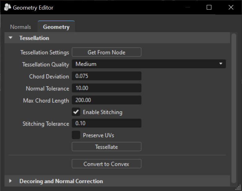
Tessellation
Provides the functionality for re-tessellation of surface (NURBS) data in the scene.
Tessellation Settings – Reads the settings that were used last time this object was tessellated.
Tessellation Quality - Uses the selected preset to determine the approximate tessellation quality. The other option values, such as Chord Deviation, Normal Tolerance, etc. automatically adjust, based on the selected quality. Displays different presets to help you choose reasonable settings, if you are a casual user.
Tessellation Quality Coarse Low Medium High Chord Deviation 1.00 0.15 0.075 0.037 Normal Tolerance 30.00 20.00 10.00 7.5 Max Chord Length 400.00 300.00 200.00 100.00 Enable Stitching Yes Yes Yes Yes Stitching Tolerance 0.10 0.10 0.10 0.10 Chord Deviation - Sets the maximum deviation between the NURBS surface and tessellated surface. A low value results in a more accurate polygon model, but increases the number of triangles.
Normal Tolerance - Determines the allowed normal deviation between the normals on the endings of a tessellated edge.
Max Chord Length - Defines the maximum edge length of the generated polygons. Long polygon edges are not shaded smooth within the Render Window. This setting is helpful to avoid such faceted effects.
Enable Stitching - Avoids the ragged edges of a tessellated representation within the Stitching Tolerance. When a surface is tessellated, this process re-builds existing topology and aligns the edges of selected shells to each other. Stitching is required to smooth the edges.
Stitching Tolerance - Sets the tolerance where two adjacent edges are considered to be touching and should be stitched together.
Preserve UVs - Preserves UVs when enabled. If the geometry is re-tessellated, its UV coordinates can be preserved by checking Preserve UVs in the Retessellation dialog. The UV layout will be transferred from the old to the new tessellated surfaces after tessellation is finished.
Note:When there are UV cuts within a surface, these cuts might not be properly reconstructed after re-tessellation. The algorithm will create a cut in the area of the original cut, but depending on how the triangulation has changed, it can look different. For example, the cut can appear as a jagged line, instead of a straight one.
Note:Edge constraints (see Constraint U / Constraint V) are not kept on retessellation.
Tessellate - Tessellates the geometry based on the settings in this section. Once all parameters are set, click this.
Convert to Convex - Converts concave polygon primitives into convex polygons, which are polygons with interior angles more than 180 degrees. Concave polygons may cause problems during rendering.
Decore & Correct Normals
Decoring removes redundant geometry that is inside other geometry, like screws and mountings inside a door covering. Since it is not visible and won't be seen when rendered, decoring makes the file lighter and reduces render time. A virtual camera flies around the selected object, takes screenshots, and depending on your settings, removes or ignores non-visible geometry, or sets the normals to B-Side.
Access geometry normals (or use vrdGeometryNode, set/getNormals), set the correct face normals (or use vrDecoreService), and select your decore settings.
- Quality Resolution - Defines the resolution of the images taken. A higher resolution gives more precise results.
- Quality Steps - Defines the number of images taken during the analysis. A higher value gives more accurate results.
Correct Wrong Normals - Flips polygon normals pointing away from the camera, if they are encountered during the analysis.
Note:As of 2022.3, you can flip normals at the triangle level without "removing" other triangles.
- Decore - Enables the decoring and parameters for defining this behavior.
Decore Mode - Defines the action to be taken, when geometry is determined to be inside another and non-visible. Choose from the following:
Transparent Objects - Determines how objects behind transparent objects are handled. Select from the following:
Ignore - Transparent objects are ignored (i.e., they do not occlude other objects and they are not occluded by other objects). (Fastest mode)
Treat as Transparent - Transparent objects will not occlude other objects, but they can be occluded by non-transparent objects. (Slower, but most accurate mode)
Treat as Opaque - No special handling for transparent objects, they are treated as opaque.
Sub Objects - Determines how sub-objects are factored in when decoring. When neither is enabled, sub-objects are not changed and decoring only happens at the object level.
- Components - Works on the component level for shells.
- Triangles - Works on the triangle/polygon level for meshes.
Start - Once all parameters are set, click Start to begin the decoring process.
For Python for decoring, see vrDecoreService, vrdDecoreSettings, and vrGeometryTypes.