
Browser overview
Learn about the design Browser and organization of design elements and objects in Fusion.
The Browser is structured differently and can contain different types of object depending on the design type.
- Part Design: A design where you model a single component comprised of bodies
- Assembly Design: A design where you create or insert other designs as external components, then define relationships between them to create an assembly.
- Hybrid Design: A flexible design where you create and model internal components, insert other designs as external components, then define relationships between them.
Elements of a design
The assembly is organized in the Browser.
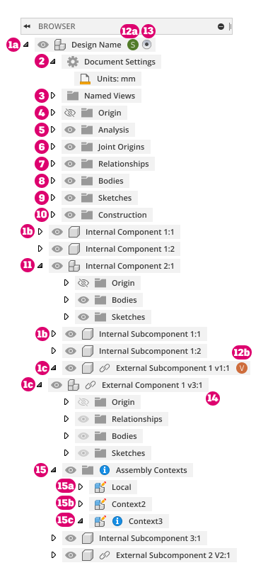
- Components: Contain and organize the elements of your design. All components can contain an origin, construction geometry, sketches, bodies, and joint origins.
 Default Component: The top component in every design. In addition to the elements that all components can contain, the default component also contains document settings, named views, analyses, and joints for the entire assembly.
 Internal Component: Contained entirely within the current design.
 External Component (xref): Contained in a separate design and referenced into the assembly in the current design. Can contain assembly contexts created during Edit In Place.
 Document Settings: Controls the units for the assembly.
 Named Views: Contains all standard and custom named views for the assembly.
- Origin: Contains the origin point, X/Y/Z axes, and XY/XZ/YZ planes associated with a component.
- Analysis: Contains analyses created in the assembly, including those created with the Section Analysis tool and surface analysis tools.
- Joint Origins: Contains joint origins associated with a component.
- Relationships: Contains assembly relationships associated with the assembly, used to define the relative position and motion between components.
- Bodies: Contains 3D bodies associated with a component.
- Sketches: Contains design sketches associated with a component, which drive and define bodies.
- Construction: Contains construction geometry associated with a component, which aid the process of creating sketches and bodies.
- Subassembly: Any component with additional components nested within. The top-level component is the Parent Component. Any component nested within is a Child Component.
 Avatar with Reservation Badge: Project member is editing the design or external component, and it is reserved by the project member to prevent design conflicts.
- Project member 1 is editing and reserved the active design.
- Project member 2 is editing and reserved an external component in the active design.
 Activated Component: The component you are currently working in. Click the radio button next to any component to activate it.
 Edit In Place: Activates and edits an external component in context without leaving the current design.
-
 Assembly Contexts: Contains assembly contexts associated with a component, which define relationships between components during Edit In Place.
 Local Context: Represents external component as the design would appear if you opened it in its own document tab. It maintains its own set of positions for child components.
- Assembly Context: The connection between a parent design and an external component at a specific point in time. Holds positional information related to the assembly.
- Out-Of-Sync Assembly Context: Right-click and select Synchronize Assembly Context to update associative design changes.
Object visibility
In the Browser, you can use the visibility icon ![]() /
/ ![]() to show or hide objects in a design in Fusion.
to show or hide objects in a design in Fusion.
Visibility states:
 The object displays in the Canvas.
 The object is hidden and does not display in the Canvas.
Component and body visibility
When components are placed or created in place in assemblies, they are automatically visible. You can toggle the visible status of components as your needs change. For example, you can:
- Make an assembly, component, or body not visible so that it is easier to work on new geometry.
- Isolate an assembly, component, or body to make navigating and modifying a particular piece of geometry easier.
- Show all to bring the entire design back to visibility quickly.
Visibility overrides in assemblies
External Components that are referenced into an assembly inherit their visibility from the external design. In the assembly, you can override the visibility of External Components and the objects within them.
When you adjust the visibility of an object in an external component, the visibility of that specific object is overridden in the assembly.
The visibility is not changed in the external design. If the external component is referenced in any other assembly, the default visibility is still inherited from the external design, unless you override the visibility in the other assembly as well.
Objects that can be overridden:
- Components
- Bodies
- Sketches
- Construction geometry
- Folders (Bodies, Sketches, and Construction only)
Objects that cannot be overridden:
- Origin folder
- Joints folder
When you hover over the visibility icon next to an object, a tooltip displays if the visibility is overridden in the assembly.
You can click the visibility icon to remove a specific visibility override or you can use the Remove Visibility Overrides tool in the Browser's context menu to remove all visibility overrides from an assembly at once.
Object opacity
You can adjust the opacity of objects to make them transparent while you focus on specific areas of your design. You can select a opacity value from the list or specify a custom percentage value.
Isolate objects
You can isolate selected bodies or components and hide all other objects to focus on a one or more objects. When you unisolate an object, visibility is restored to all objects that were visible before you used the isolate. Any objects that were hidden before isolation remain hidden.
Object selection
Selectable status
You can make a component selectable or unselectable in the Canvas. When you make an object unselectable, the icon in the Browser displays a badge on the component type icon:
 Component is unselectable.
 Assembly is unselectable.
Selection sets
Use selection sets in the Browser to save and reuse groups of selected objects.