My Learning - Design workspace
Here are the My Learning campaigns for the Design workspace.
Design > Solid > Create a solid body
Create a solid body
Create a solid body using primitive shapes. Click Design > Solid > Create > Box. Select a plane you want to create the body on. Select the center point as the first corner of the box. Specify the size of the box 50 mm x 50 mm x 50 mm. Keep the Operation as New Body. Then click OK.
Design > Solid > Create fillets
Create fillets
Click Design > Solid > Modify > Fillet.
In the Fillet dialog, from the Type drop-down list, select Rule Fillet and set the Rule to All Edges. Select the top face of the body, set the Radius to 5 mm and click OK.
Design > Solid > Create an axis
Create an axis
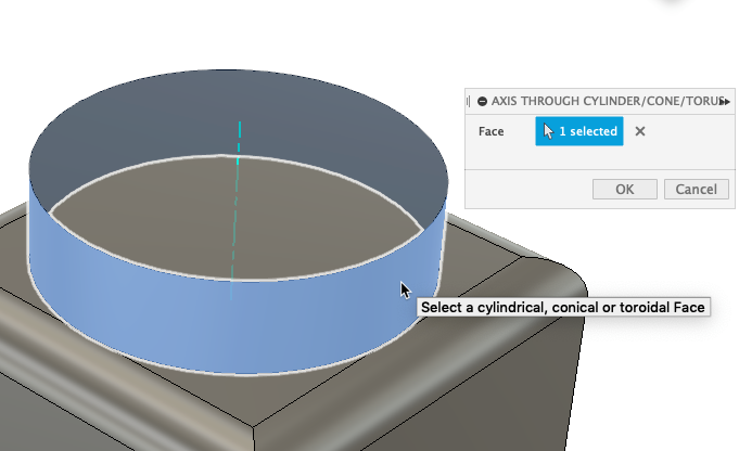
Click Design > Solid > Construct > Axis Through Cylinder/Cone/Torus.
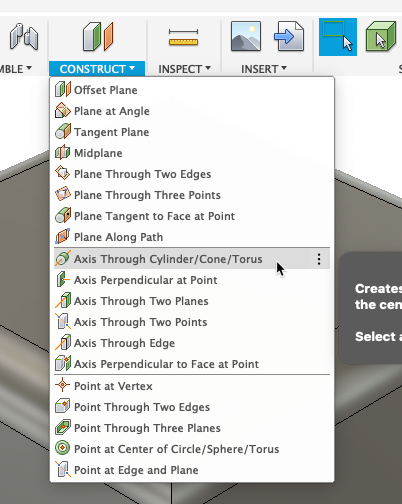
Select the cylindrical face and click OK.
Design > Solid > Create a hole
Create a hole
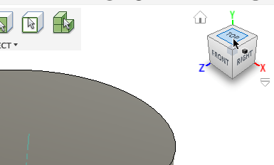
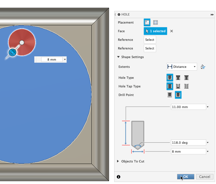
Click the Top of the ViewCube to display the top of the model.
Click Design > Solid > Create > Hole.
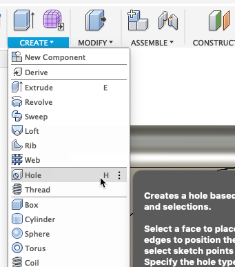
Select the Cylinder's top face and create a hole with a Radius of 8 mm. Drag the hole closer to the cylinder's edges. Click OK.
Design > Solid > Create a pattern
Create a pattern
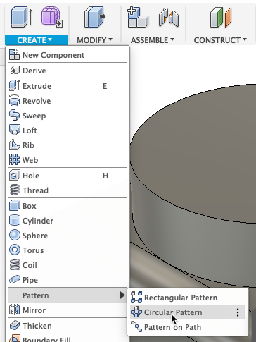
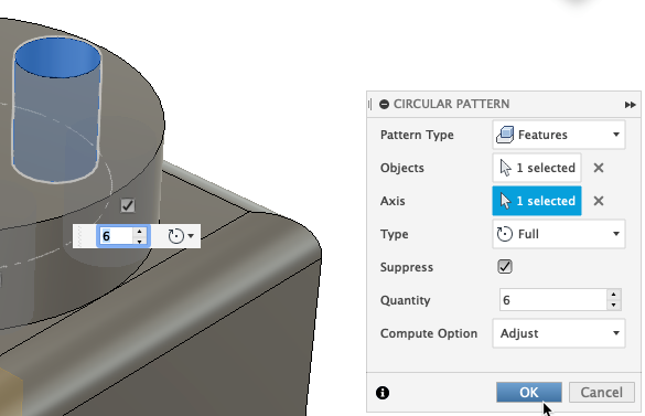
Click Design > Solid > Create > Pattern > Circular Pattern.
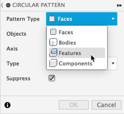
In the Pattern dialog, set the Pattern Type to Features and select the hole feature from the Timeline.
Next to Axis, click Select. In the Browser, under Construction, select Axis 1.
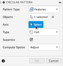
Set the Quantity to 6 and click OK.
Design > Sketch > Create a sketch
Create a sketch
- Click Design > Solid > Create > Sketch.
- Select the initial plane or face to begin the sketch.
Design > Sketch > Select 3D Sketch
Design > Sketch > Start a sketch
Start a sketch
Select one of the sketching tools supported by 3D Sketch.
- Line
- Arc
- Spline
- Rectangle
- Circle
- Ellipse
- Point
- Text
- Conic Curve
Design > Sketch > Adjust the manipulator
Adjust the manipulator
To switch to a different sketch plane, select it: XY, YZ, or ZX.
To rotate the sketch plane, drag any rotation handle.
Design > Sketch > Place first sketch point
Place first sketch point
To place the first point, click anywhere on the active sketch plane.
To restrict the point along an axis, place the mouse pointer along the axis until its extension line displays, then click to place the point.
Design > Sketch > Place more points
Place more points
- To place the next point on the same sketch plane, click anywhere on the active sketch plane, or type rotation and distance values.
- To restrict the point along an axis, place the mouse pointer along the axis until its extension line displays, then click to place the point or type a distance value.
- To place the next point on a different sketch plane, adjust the 3D Sketch Manipulator, then click anywhere or type rotation and distance values.
Design > Sketch > Finish a sketch
Design > Surface > Patch surfaces
Patch surfaces
You can create boundary patches to form a continuous quilt or create a solid. Click Design > Surface > Create > Patch.
Design > Surface > Extrude surfaces
Extrude surfaces
Select a line or edge of a solid model to create an extruded surface. This can be used as reference geometry or be helpful in driving toolpaths in the Manufacturing workspace.
Click Design > Surface > Create > Extrude.
Design > Surface > Loft surfaces
Loft surfaces
Loft on the Surface tab is similar to a Loft on the Solid tab. With Surface, Loft just creates surfaces that can then be thickened to create solid bodies. Click Design > Surface > Create > Loft.
Design > Surface > Stitch surfaces
Stitch surfaces
Stitch (join) multiple surfaces together in a design to make a unified surface. Click Design > Surface > Modify > Stitch.
Design > Surface > Unstitch surfaces
Unstitch surfaces
Select a line or edge of a solid model to create an extruded surface. This can be used as reference geometry or be helpful in driving toolpaths in the Manufacturing workspace. Click Design > Surface > Modify > Unstitch.
Design > Surface > Trim surfaces
Trim surfaces
Select a line or edge of a solid model to create an extruded surface. This can be used as reference geometry or be helpful in driving toolpaths in the Manufacturing workspace. Click Design > Surface > Modify > Trim.
Design > Surface > Extend surfaces
Extend surfaces
Select a line or edge of a solid model to create an extruded surface. This can be used as reference geometry or be helpful in driving toolpaths in the Manufacturing workspace. Click Design > Surface > Modify > Extend.
Design > Sheet Metal > Review sheet metal rules
Review sheet metal rules
A named Sheet Metal Rule, such as Stainless steel (in) or Aluminum (in), captures these parameters and applies them by default when you create a sheet metal part. To access the Sheet Metal rules, click Design > Sheet Metal > Modify > Sheet Metal Rules.
Design > Sheet Metal > Sheet metal flanges
Create flanges
A flange feature consists of a face and a bend connected to an existing face along an edge. The Flange tool is the multitool in the Sheet Metal workspace.
With it you can create:
- Face Extrusion
- Flanges
- Contour Flanges
Design > Sheet Metal > Unfold/refold faces
Unfold/refold faces
To create cuts across bends you must unfold the part to create the cuts, and then refold it to show the formed part again. This process is done using the Unfold and Refold tools. To access the Unfold tool click Design > Sheet Metal > Modify > Unfold.

Design > Sheet Metal > Create a flat pattern
Create a flat pattern
Use a flat pattern, which is the shape of the sheet metal part before it is formed, to create drawings for manufacturing. Flat patterns show bend lines, bend zones, centerlines, and the shape of the entire part with all bends flattened and bend factors considered. Note: You can only create one flat pattern for each body.
Design > EIP > Insert an XREF
Insert an XREF
Navigate to a component in the Data Panel, right-click, then click Insert into Current Design. Note: Make sure you have saved the design if starting from new design.
Design > EIP > Enable Edit in Place
Enable Edit in Place
In the Browser, place the mouse pointer over the XREF, then click Edit in Place.
Design > EIP > Associativity to assembly
Associativity to assembly
Edit sketches and other features of the component directly.
Measure distances relative to inactive components.
Design > EIP > Create a context
Create a context
Reference geometry from the inactive components in the parent design:
- Edges, faces, points
- Dimensions and constraints
- Position
- Projection
- Termination
An Assembly Contexts folder is created in the Browser and a Context is created, which you can return to and edit again later.
Design > EIP > End Edit in Place
End Edit in Place
Click End Edit in Place to return to the parent design. Save your changes.
Design > EIP > Edit existing context
Edit Existing Context
In the Browser, expand the XREF's node. Expand the Assembly Contexts folder. Place the mouse pointer over the Context and click Activate Context. Note: You can also right-click the Context in the Timeline.