Detail specific small areas of the model directly from existing general arrangement drawings.
A functionality to enhance the way symbols are configured is also available - these are symbols used by the callout view to display relevant data about the view number, scale or drawing number.
Using the callout functionality you can create fast and precise callout views, directly from the general arrangement drawings. The command provides the same level of customization as for manual cut views, offering you the option to change the drawing style, control the scale and manually choose the points and the depth of the view.
Using the callout feature you can:
- Create the callout view.
- Customize the callout symbol and callout title using a graphical template approach instead of a label (similar to the weld templates).
Create the callout view
Command line: _ASTORDETCREATECALLOUT
- In the Labels & Dimensions tab
 Parametric views panel, click
 (Create callout view).
- The command line will prompt you to select the detail view or access the Settings using the S key, as prompted in the command line.
- Selecting the view where the callout will be created will perform a fast view creation, with no extra steps, using the default drawing style and scale. The callout command will ask for two points that represent the opposite corners of a boundary rectangle which defines the view size for the callout view. The depth of the callout view will match the depth of the main view, so if for example, the callout view is created on an Elevation GA with a 2' Front/Rear depth, the callout view will use the same 2' Front/Rear depth.
- Using the S key, you access the View settings dialog that contains the overrides for the view request and scale used by Advance Steel to generate the callout view.
The view requests provide all the settings required for creating the callout view (object presentation, labeling rules, line type, and dimensions). The view requests are located in the Drawing style manager, for each drawing style. You can use the Drawing style manager to make edits to preferred view requests, if needed.
Option Description Scale This combo box contains all the scales available in Advance Steel and one default scale. The default scale is an intelligent setting that uses the scale of the view selected for the callout view. Using the default scale allows you to create callout views (that use the scale of the main view) faster, without the need to manually match them afterwards. The Scale field is set to Default. Once you change the scale from this dialog, the change is saved and can be reused for other callouts created afterwards, until the dialog is accessed and the scale is changed again. Advance Steel memorizes the last used scale until you close the software, defaulting back to the Default value when you reopen Advance Steel. View This combo box contains a list of all the view requests available in Advance Steel - that are used when generating callout views. Note: The view requests are not drawing styles, they are part of the drawing style and in order to edit them, you need to have a drawing style configured temporarily in order to use such a view request for full configuration access.You can find the list of view requests available for manual cuts in the Drawing style manager, at the following level: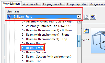
In the View settings dialog View combo box, you can choose between the Advance and User view categories:

By default, Advance Steel sets the view request from a series of defaults found in the Management Tools application: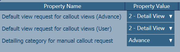
- Default view request for callout views (Advance)
- Default view request for callout views (User)
- Detailing category for manual callout request
Once you change a view request from the list, it is saved in the local memory and reused for the callout view command until you exit Advance Steel, similarly to the scale setting.
- When you are done making the settings, click OK. This will send the command back to the first step where you are prompted to select the view or, if needed, to reopen the Settings dialog.
Customize the preferred list of detail view requests used by the callout command
You can set the preferred view requests that will display in the Settings / View settings dialog. Using this type of configuration will make available a short list of view requests when creating the callout views (and also manual cut views).
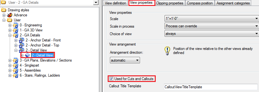
To add a specific detail view request to the preferred for Cut / Callout view list:
- Open Drawing Style Manager and select the specific view.
- On the View definition level, access the View properties tab.
- Check the Used for Cuts and Callouts option.
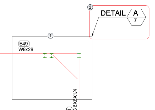
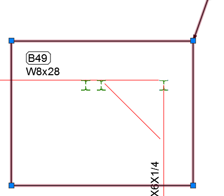
Callout symbol representation on the main view
When a callout view is created, a callout symbol is also inserted on the main view. This symbol is composed of a frame ( ) that defines the border of the selected callout view size and a label symbol (
 ) that can display information about the view:

In the Frame tab you can change the color and line type of the boundary rectangle.
In the Representation type tab you can change how the frame is drawn:
| Option | Description |
|---|---|
| Rectangle | The default setting, which represents a 1:1 match to the callout view size. |
| Circle | A circle that fits the rectangle inside. The callout view will remain a rectangle in shape, while this option only creates a virtual circle for a better representation. |
| Off | The frame will be turned off, but the callout view will remain unchanged. It can be turned back on by right-clicking on the callout symbol (which remains visible) and selecting Advance Properties from the contextual menu to access the Callout frame dialog. |
The callout frame symbol also offers 4 grip points, which you can use to change the size of the callout view once the callout is created.
You can configure the default settings for all the options available in the Callout frame symbol dialog, using the Management Tools application Defaults category, using the following properties:
- Drawing-Presentation Colors Callout frame color.
- Drawing-Presentation General Callout frame representation mode.
- Drawing-Presentation Linetypes Callout Frame linetype.
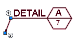
- Moves the callout symbol label.
- Changes the position of the leader line arrow.
The position of the symbol is kept during update, and the automatic positioning on the top-right corner during the initial creation of the callout view will no longer be taken into consideration.