Align labels on drawings using an existing reference label and a set of predefined rules.
To access the Align labels to reference command:
- Right-click on a label in a drawing.
- Select Align labels to reference from the contextual menu.
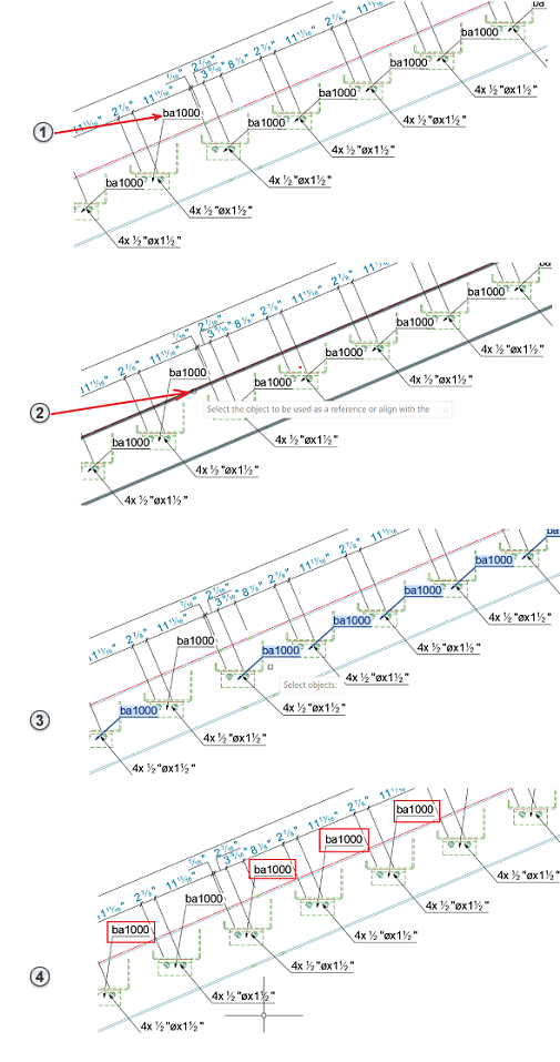
Step 1: Select the Reference Direction
-
An Advance Steel object detailed on the sheet: If you use this option, the reference direction will be the X direction of the selected object. For beams, this would be the system line direction. If a plate is selected, then the plate X direction will be used. To use a detailed Advance Steel object as a reference, select the object when the command prompts you to select the object to be used as a reference. Other elements that are supported are: curved beams, polybeams, folded plates, folded beams, and gratings.
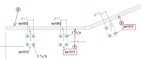
Note: For polybeams, the direction used by the command is determined by the polybeam segment closest to the reference label:

- Label 1
- Label 2
- Polybeam
If you select Label 1, the reference direction is provided by the horizontal polybeam segment. If you select Label 2, the reference direction is provided by the sloped polybeam segment
- The X or Y sheet directions: Type "X" or "Y" in the command line, when asked to select the object to be used as a reference. The command will use the horizontal or the vertical direction of the sheet as a reference.
- An AutoCAD line: Similarly, to the object selection, the command will also accept a line as a reference, instead of an Advance Steel object. The line option will allow any type of arrangement method, for the cases when the direction does not match any objects on the Advance Steel drawing.
Step 2: Select the Labels to Align
For this step, the command will accept any number of other labels that will be aligned to the reference label. You can select the labels by clicking on them, or by using a blanket selection. The command will only align labels, so the selection can contain other objects or annotations that will not be moved.
- It determines the distance from the reference label to its host object as the perpendicular direction from the label insertion point to the object's closest visible or hidden geometry line.
- It takes the reference direction and projects it from the reference label insertion point.
- It aligns the labels with their insertion point, along the reference direction that originates from the reference label.
Because the reference direction is translated to the reference label, this reference direction can be anywhere in the model. Its location will not affect how the labels will be aligned, as they will still use the reference label position for this.
|
 |