Learn about the default settings for detailing the camera symbol, available in the Management Tools.
In the Home tab  Settings panel, click
 (Management Tools).
| Default | Description |
|---|---|
| Detailing camera representation type | In the Management Tools Defaults Drawing-Presentation General Detailing camera representation type, select the representation type from the drop-down menu (rectangle or circle).
|
This default setting controls the graphical presentation of the symbol:
|
|
| Camera symbol dwg file name |
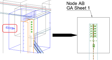
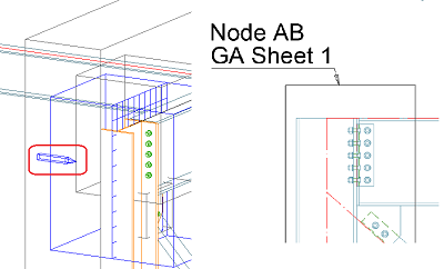
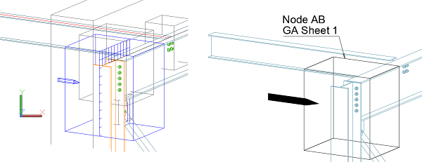
Besides the rectangle or circle representation, the camera symbol has a second graphical component - the arrow symbol. This graphical element will show how the camera view direction is set to the model object. To set the graphic for this arrow: In the Management Tools This default controls the resource dwg file from which Advance Steel reads the graphics. The file is stored in C:\ProgramData\Autodesk\, under […\Advance Steel [VersionNumber]\[ContentLanguage]\Shared\Support\Symbols\] The standard symbol will contain an AutoCAD Hatch and Polyline that describe an arrow, created in the yz plane of the dwg file. This symbol graphic is then inserted at a 1:1 scale in the detail drawing Advance Steel creates with the camera symbol presentation. |
|
To edit the camera symbol dwg file:
|
|
|
Important: The arrow is created only when the viewport of the general arrangement drawing is perpendicular on the model camera direction, or isometric to it. If the viewport is along the camera view direction, then the arrow symbol will not appear on the drawing.
|
|
| Color of object labels in details | In the Management Tools Defaults Drawing-Presentation Color Color of object labels in details, select the default color for the camera symbol label from the drop-down menu.
|
| Color of symbols for visible objects in details | In the Management Tools Defaults Drawing-Presentation Color Color of symbols for visible objects in details, select the default color for the camera symbol graphic (circle/rectangle + arrow) from the drop-down menu.
|