To measure a single point within a point cloud:
- Open a Geometric group in the Sequence Tree.
- Click Geometry tab > Points panel > Probed > Point-Cloud Single Point.
The Point-Cloud Single Point dialog contains the following areas:
Name — Enter a name for the item. The name is used in the inspection sequence, in the Report and Info tabs, and when referencing the item in other items.
Use nominals — Select this check box to enter or change the item nominals, and to compare the item measurements to their nominal values. Deselect this check box to disable comparisons with the item nominals.
When this check box is selected, an in-tolerance
 or out-of-tolerance
 indicator is displayed on the measured item's icon in the inspection sequence; the border of the item
label is coloured to indicate whether the measurements are within tolerance; and the tolerance, nominal, deviation, and error values of the item are shown in the report.
indicator is displayed on the measured item's icon in the inspection sequence; the border of the item
label is coloured to indicate whether the measurements are within tolerance; and the tolerance, nominal, deviation, and error values of the item are shown in the report.
When this check box is deselected, the Nominal boxes are disabled, no tolerance indicators are displayed and no tolerance, nominal, deviation, and error values are shown in the report for this item.
 and select
From CAD Entity. To replace the nominals with the item's measurements in the current Measure, click the button and select
From Active Measure.
and select
From CAD Entity. To replace the nominals with the item's measurements in the current Measure, click the button and select
From Active Measure.
Visible — Select this check box to display the item in the CAD view.
Output in report — Select this check box to include the item in the report.
Coordinate system — Select the alignment relative to which the item's measurements are to be reported.
To specify the alignment during the inspection, select <Active Alignment>. You can then select the alignment from the Active alignment list, or by adding an Active Alignment item to the inspection sequence.
Search distance — Enter a value in the box to specify the maximum distance from the nominal position of the feature that you want PowerInspect to search.
Normal vector — Choose an entry in the Method list to specify how you want to display the normal vector. Select:
- No normal vector to not display the normal.
- Normal along datum axis to display the normal along a specified axis. In the Coordinate type list, select Cartesian, Apparent angles, or Spherical to specify the axis direction, or select X/X-, X/X+, Y/Y-, Y/Y+, Z/Z-, or Z/Z+ to use a major axis.
- Normal along feature axis the normal along the feature of a selected item. Select the item in the list, or click
 to select the item from the CAD view using the mouse.
Target point — Enter the nominal and tolerances for the position of the point.
Distance to target point — Enter the nominal and tolerances for the distance  between the target point and the measured point.
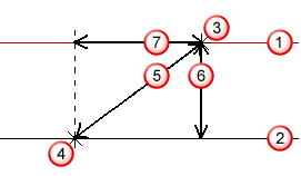
 Nominal surface
 Actual surface
 Nominal single point, which is the target point
 Measured point
Distance to target point
 Distance to target plane
 Distance on plane
Distance to target plane — Enter the nominal and tolerances for the normal distance between the measured point and the plane of the target point.
This distance can be positive or negative, depending on whether the measured point is above or below the nominal point.
Distance on plane — Enter the nominal and tolerances for the distance along the plane of the target point between the measured point and the target point.
Point sources — Select this tab to use probed points from other items to measure this item.
For example, you can use the tab to create a measured cylinder by combining measurements from probed circles at the top and bottom of the feature.
To specify the sources for the probed points, select one or more items in the
Available sources list, and then click
 to add them to the Selected
sources
list.
to add them to the Selected
sources
list.
To remove sources, select the items in the
Selected sources list, and then click
 .
.
Click OK to close the dialog and save your changes.