A licence with an unlimited number of elements is required to run simulations or mesh a 2D zone or Mesh zone with Subgrid Sampling.
|
From version 2027.2 onwards, Subgrid Sampling is no longer a Tech Preview. Users of earlier versions of InfoWorks ICM will continue to use the Tech Preview version, which supports a limited set of modelling capabilities, network objects and mesh functionality, as listed in Supported items below. |
An outline of how to include Subgrid Sampling in an InfoWorks 2D model is listed below. See Tips for using Subgrid Sampling below for some recommendations when using this option.
- In the
properties for an
InfoWorks 2D zone:
- Check the Subgrid sampling box.
- Specify the mesh resolution (triangle size) for Subgrid Sampling triangle area, and ensure that this is less than the specified Maximum triangle area.
Topographical features below the specified subgrid triangle size may be ignored by ICM so consider carefully what is an appropriate area to use.
- Ensure that Mesh generation is set to Clip meshing.
- If a Mesh zone is included in a 2D zone, and you want to use its Subgrid Sampling
properties, rather than the 2D zone's ones, you can:
- Check the Override 2D zone Subgrid Sampling box.
- Check the Subgrid sampling box.
- Specify the mesh resolution for Subgrid Sampling triangle area, and ensure that this is less than the Mesh zone's specified Maximum triangle area.
- Select the applicable 2D zone on the GeoPlan and generate its mesh. Any polygon and polyline objects that represent voids, break lines and walls, should be included in the mesh.
- Check the mesh log. See
Manage Mesh Results dialog for details.
If there are any objects or functionality that are not currently supported when using Subgrid Sampling, the mesh will fail and a suitable message will be included in the log.
Correct any errors and re-mesh the 2D zone.
If the mesh was generated successfully, load the mesh to the network. - Validate the network that includes the subgrid 2D zone. Correct any validation errors.
- Run a simulation for the network that includes the subgrid 2D zone.
If there are any objects or functionality that are not currently supported when using Subgrid Sampling, the simulation will fail and a suitable message will be included in the Log result files for the applicable simulation.
Correct any errors and re-run the simulation.
- Analyse the results. The following subgrid-specific results are included for 2D zones and
Network Results Point 2D objects (if any were included in the network):
- Mean depth (time-varying) and Max mean depth and Min mean depth (summary)
- Volume (time-varying), and Max volume and Min volume (summary)
- Subgrid flag (summary). Only available for 2D zone results.
See 2D Zone Results Data Fields and Network results points (2D) results for descriptions of the result attributes.
You can use the Property button on the
GeoPlan toolbar to view all of the results. The Mean depth and Volume results can also be displayed using, for example, the
pick graph
button on the
GeoPlan toolbar to view all of the results. The Mean depth and Volume results can also be displayed using, for example, the
pick graph
 and
pick grid
and
pick grid
 buttons on the
Results toolbar.
Note: Time-varying result attributes for 2D simulations are displayed on a 2D element basis. For subgrid 2D elements, these are shown at triangle level for depth and speed.
buttons on the
Results toolbar.
Note: Time-varying result attributes for 2D simulations are displayed on a 2D element basis. For subgrid 2D elements, these are shown at triangle level for depth and speed.You can also use polygon themes for 2D zones for displaying these results on the GeoPlan. See Special polygon themes for 2D zones for details about the themes you can use.
Note: For 2D results, these themes are presented on an element-by-element basis for standard 2D models (non-subgrid 2D elements). For subgrid 2D elements:- The Depth theme represents the depth at triangle level, where the triangle depth is calculated as the free surface elevation minus the triangle ground level or the minimum level in the volume/level table for the 2D subgrid element, whatever is higher.
- The Speed theme represents the velocity at triangle level, where the velocity at a triangle will be set to the reported speed at the 2D elements if the triangle depth is > 0. Otherwise the velocity will be 0 at the triangle.
Tips for using Subgrid Sampling
The following recommendations apply when using Subgrid Sampling.- Wave Propagation on Slopes
Subgrid Sampling can sometimes lead to over-rapid propagation speeds, especially at flows going down slopes unimpeded. See Wave propagation speed for details. In general, it is worth using caution when using the Subgrid Sampling method in scenarios with shallow water flowing downhill, for example, when rainfall is applied directly to the mesh in hilly areas. We recommend that Subgrid Sampling is not used for the 2D zone in such cases (i.e. remove the check from the 2D Zone's Subgrid Sampling box), and instead use the Subgrid Sampling method for a Mesh zone for the area of interest, low-lying regions or areas where the flowpaths are clearly defined.
- Alignment with Topographic Barriers
Be careful not to make subgrid 2D elements too large where there are topographic barriers. See Blockage effects for details. Subgrid Sampling only accounts for topographic barriers on the boundaries of the elements, and so, in cases where an embankment or crest runs through the centre of a subgrid 2D element, the flow may experience "tunnelling" and bypass the barrier. It is recommended to use breaklines along any significant topographic crests to ensure the faces of subgrid 2D elements are aligned with the crests.
- Crest Levels for Height-Based Linear Structures
When linear structures define their crest using height above ground and Subgrid Sampling is enabled, the specified height is applied relative to the highest of the ground levels of the two computational elements either side of the structure.
For adjacent subgrid 2D elements, this corresponds to the highest of:
- the 2D face ground level, and
- the minimum level entry in the volume/level table of the adjacent subgrid 2D element.
If the face ground level is below the lowest entry in the volume/level table, it is reset to that minimum level before the crest elevation is calculated.
This behaviour may result in differences in simulated flows and water levels near affected structures compared to earlier versions.
- Subgrid Triangle Resolution
You should use subgrid triangle resolutions of at least an order of magnitude smaller than the 2D element size. The subgrid triangle size is used as a reference area to remove initial small entries on the volume/level tables. This process is essential to keep stability in the 2D engine computations. If the number of subgrid triangles per 2D element is very small, the removal of small triangles may introduce a slight volume error in the volume/level tables. This effect becomes unnoticeable as the number of subgrid triangles per 2D element increases.
There is little computational cost to the 2D engine solver to have many subgrid triangles within a 2D element. Therefore it is recommended to try to match the ground model resolution with the subgrid triangle size. Note however that increasing the subgrid triangle resolution has a computational cost when it comes to meshing and so may increase the mesh generation times.
- Network Results Lines in Subgrid Models
If you intend to use a Network results line (2D) with Subgrid Sampling to check flow results, ensure that the line covers the whole flow exchange area.
This is particularly relevant in river models when using large subgrid 2D elements to represent the river bed as it can lead to the tunneling effect (mentioned previously), where a portion of the river flow does not follow the river bed but is exchanged laterally between subgrid 2D elements.
An example is shown below:
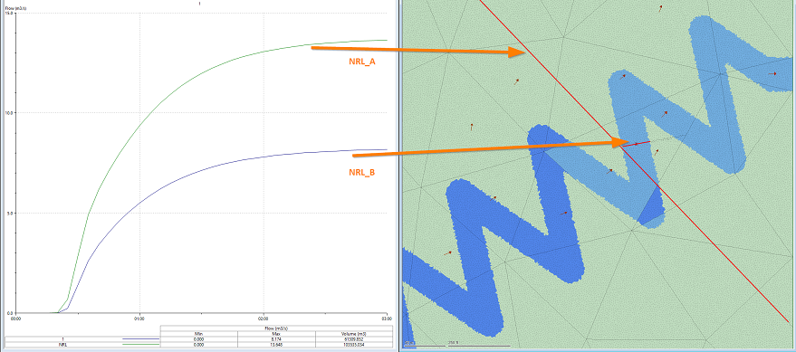
In this example, the expected flow through the river bed is 13.5m3/s. This is captured correctly when using a network results line (2D) covering all the 2D elements that transfer flow downstream (see NRL_A and the green graph line in the example). However, the smaller network results line (2D) that is drawn only on the river bed (NRL_B) does not fully capture the total flow (as shown by the purple graph line). This is because the size of the subgrid 2D elements is too large with respect to the river bed and flow "tunneling" occurs in the meander where this line (NRL_B) is located.
Therefore, when using Subgrid Sampling for river modelling, it is recommended to use a 2D element size smaller than the river bed.
- CPU and GPU Performance Considerations
Using a GPU card when running 2D simulations is already very efficient, and so any speed increases when using Subgrid Sampling over non-subgrid models is less pronounced for GPU solutions compared to CPU solutions. Using Subgrid Sampling with a GPU card is often about 5-10 times faster than non-subgrid of a equivalent subgrid triangle resolution, whereas on the CPU it can be as much as 40-80 times faster. This is, of course, dependent on the circumstances of the scenario being modelled.
- Elevation linkage with Connect 2D nodes
When using the Elevation 1D-2D linkage basis in combination with Subgrid Sampling, nodes located in dry areas of a 2D element may still generate inflow if the elevation in the 2D zone is above the reference level at the node.
This occurs because the elevation value is used directly to set the water level at the connection point rather than the local depth of the triangle.
See Node Data Fields - 1D-2D linkage basis for details of how the reference level is defined.
Supported items
The following set of modelling capabilities, network objects and mesh functionality, can currently be used with Subgrid Sampling:
- 2D Boundaries.
- 2D Conduits.
- 2D Culverts.
- 2D Line Connect objects.
- 2D Nodes.
- 2D point sources/line sources
- 2D zones.
- Apply rainfall profiles to 2D meshes.
- Base Linear Structures (2D), including RTC definitions in Section Data.
- Bridge Linear Structures (2D).
- Connect 2D Nodes.
- Infiltration Surface (2D).
- Infiltration Zone (2D).
- Initial Conditions 2D, when the Variable is set to Hydraulic.
- Initial State Simulations.
- Inline bank, when acting as a 1D-2D link.
- Mesh generation including geometric features, such as Voids, Breaklines and Walls.
- Mesh zone.
- Network Results objects.
- Permeable Zone (2D).
- Porous Polygons.
- Porous Walls.
- River Reach - Bank Flows, when the river bank is connected to a 2D zone.
- Roughness Zones.
- Sluice Linear Structure (2D).
- Steady State functionality.