
Civil Tools
When viewing Civil 3D drawings in Autodesk Construction Cloud, you can perform alignment awareness and civil infrastructure-specific design review workflows. The available tools enhance the design review process for infrastructure projects by allowing you to interact with models in the context of project alignments.
You can navigate along baseline geometry, track their position with stationing information, create cuts perpendicular to the baseline, and query the model. This functionality empowers a broad range of stakeholders, including BIM/CAD Managers, Project Managers, QA/QC personnel, and civil/design engineers. They can effectively collaborate on infrastructure projects within Autodesk Construction Cloud. This enhanced workflow streamlines access to critical model information, enabling more efficient and inclusive design reviews.
In addition, creating an issue while there is geometry selected in the Civil Tools panel will store the selection as part of the issue.
In this article, you'll learn how to:
- View Civil 3D Drawings
- Understand Alignments in Civil Tools
- View and Track Alignment Profile Stations
- Cut Geometry at Stations
- Measure Station Offsets
- Create Issues with Civil Alignments
View Civil 3D Drawings
Learn how to begin viewing Civil 3D drawings in Autodesk Construction Cloud.
Upload a Civil 3D drawing to the Files tool with one of the following methods:
Once processed, the icon for the file changes. Open the drawing.
On the left navigation menu, click
 Sheets & Views and select a 3D view from the 3D tab.
 On the left navigation menu, click
 Civil tools to open the Civil tools panel.
Use the Civil Tools panel
Explore the tools available to review your Civil 3D model in Autodesk Construction Cloud.
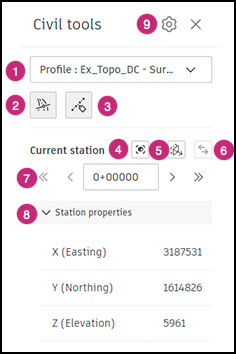
- Alignment profile list: Selects and highlights a specific alignment profile in the drawing. A list of the project geometry displays, organized by alignment and profile. Selecting a profile selects the corresponding 3D shape. While 2D profile lines may be visible, the tool works with the 3D geometry. Alignment names provide context to select the 3D geometry.
 Station tracker: Displays a highlighted line at the currently selected station that is perpendicular to the alignment. The station is labeled at its position. Selecting this tool shows or hides the station tracker.
  Station labels: Displays other stations with labels along the alignment. Labels display dynamically, adjusting to both zoom level and view orientation. Selecting this tool shows or hides the labels.
  Zoom to current station: Centers and zooms the current view to the selected station. This tool is enabled when the station tracker is visible.
  Cut model geometry: Clip all geometry before the selected station with a perpendicular plane. This tool is enabled when the station tracker is visible.
  Reverse cut direction: When Cut model geometry is enabled, this inverts the clipping plane to all geometry after the selected station. This tool is enabled when the station tracker is visible.
 - Station navigation: Navigates back (<) and forth (>) between the stations, or to the beginning (<<) and end (>>) stations of the alignment.
- Station properties: Displays the easting, northing, and elevation coordinates of the currently selected station.
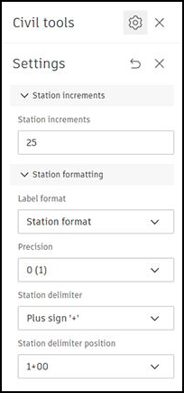
 Settings: Opens the Civil tools settings panel. Define the station increments along the alignment and specify the station label formatting.
Understand Alignments in Civil Tools
Recognize, highlight, and select linear geometry from infrastructure design.
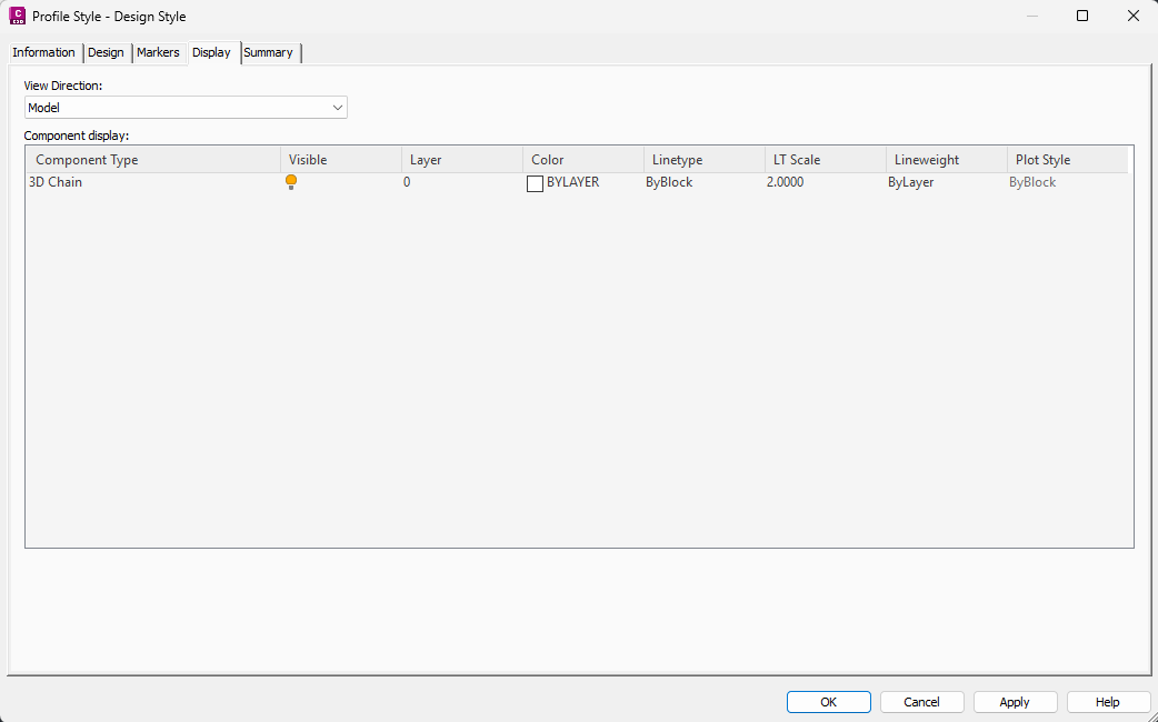
While “alignment” is commonly used to describe linear geometry in Civil 3D, the actual 3D shape represented is the profile, which combines both horizontal and vertical geometry. Because of this, the civil tools require the profile geometry of the drawing to be visible in the 3D view. This is accomplished by setting the 3D Chain to Visible under the Model View settings of the Profile Style in Civil 3D.
Select an alignment
The drop-down menu at the top of the Civil tools panel lists all profiles in the drawing organized under their respective alignment. When selected, a profile displays with a highlight.
If the list is exceedingly long, use the search function to filter the list by character strings.
View and Track Alignment Profile Stations
In Civil 3D, a station is a point along an alignment that represents a specific distance from the beginning of that alignment. They provide a way to reference and locate features, points, and other elements along an alignment. This is crucial for design, construction, and documentation. Civil tools offer a means of displaying and reviewing stations in the 3D model.
Display stations along an alignment profile
Below the alignment profile drop-down menu, click the Stations labels icon ![]() .
.
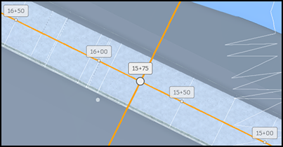
Station labels are placed at regular intervals along the alignment profile. This spacing intelligently adapts to the current zoom level and view orientation.
Click ![]() Station labels again to hide stations.
Station labels again to hide stations.
Specify step interval and label formatting for stations
At the top of the Civil Tools panel, click the Settings icon  . The Settings let you specify station step intervals and label formatting options.
Display the station tracker
Position along the alignment can be tracked by defining and editing the current station.
Below the alignment profile drop-down menu, click the Station tracker icon ![]() .
.
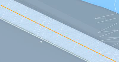
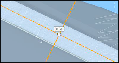
The station tracker displays at the beginning of the alignment profile as a highlighted perpendicular line. The station tracker label reports its current station position.
![]()
The Station tracker is a means of quickly identifying a specific station and it’s a perpendicular plane to the alignment profile.
Track stations along an alignment profile
There are several methods to change stations.
Manually enter a station in the current station field between the step controls.
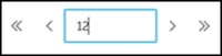
Step forward (>) and backward (<) to move the tracker to the next station increment as defined in the settings.
Jump to the end station (>>) or beginning station (<<).
Click and drag the station tracker to any point along the alignment profile.
The tracker always maintains a perpendicular orientation to its alignment profile.
Cut Geometry at Stations
A vertical cut plane, perpendicular to the alignment, can be enabled at the current station. This cut plane, which dynamically updates with the current station value, is only available when the station tracker is visible.
Create a cut plane with a station
Move the station tracker to the location to apply the cut plane.
Click the cut model geometry icon
. Any geometry before the current station will be clipped by a plane along the perpendicular station tracker. This lets you see a cross section view of your model to better review and better understand your design. (Optional) If needed, click the Reverse cut direction icon
to display the geometry before the station and clip the geometry after the station. 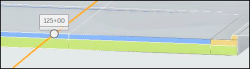
Viewing the model with the cut plane lets you access typically hidden features that can be reviewed and measured with the Measure tools.
Measure Station Offsets
Station offset measurements can be determined from a selected point in your project geometry. The Station Offset tool is available in the Measure tools of the Viewing toolbar when viewing Civil 3D drawings.
To view offsets to a station from a point:
- In the Viewing toolbar, click Measure
 and then Station Offset
  .
. - In the drawing, click a point along an object to be measured.
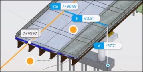
The Station Offset measurement shows the closest station point (Stn), and the horizontal (H) and vertical (V) offsets from that station to the selected point.
The measurement units follow the unit settings in the measurement toolbar.
Create Issues with Civil Alignments
In the Files tool, you can create issues in the viewer. If you create an issue while there is geometry selected in the Civil Tools panel, the selection is saved as part of the issue. When another project member opens the issue, the Civil Tools panel state is restored including the profile selection, current station, and cut plane. Visual settings such as profile highlight, station tracker, and sectioning are included in the issue snapshot.