
Create a tool assembly, view machine-side and tool-side profiles, view the holder assembly, create the cutter profile, and view and use the tool assembly.
To create the tool assembly
You create tool assemblies in the Resource Manager.
Start TruePath.
In the ribbon, go to Manage > Resources > Tools.
Click Create.
The Create Tool Components window appears. You create the holder in this window. Apply the following settings, replacing the component names with the names of your components. All component names must be unique.
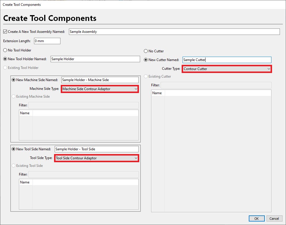
Click OK.
To create the machine-side profile
You create machine side profile from the Resource Manager.
In the Filter By drop-down menu, select Machine Side Contour Adaptor.
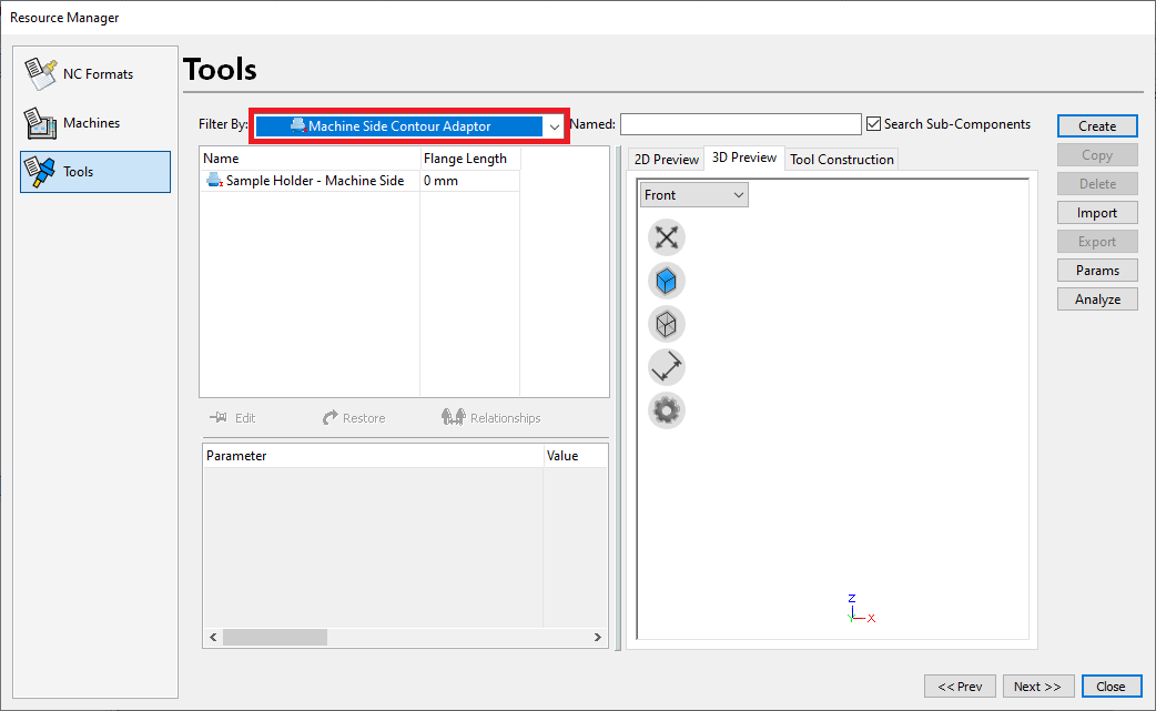
In the grid, select the machine side holder you want to create the profile for. In this example, it’s “Sample_Holder_MS”.
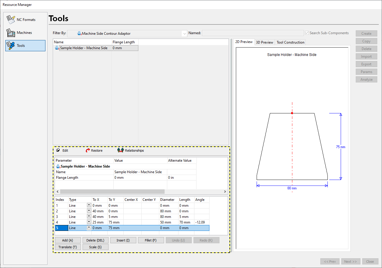
Click Edit. You see a black-and-yellow border around the holder parameters, indicating that you can edit them.
Use the Add, Delete, Insert, Fillet, Translate, and Scale buttons to create the profile.
Add – Adds a blank row to the end of the list of entities.
Delete – Deletes the highlighted row from the list of entities.
Insert – Inserts a row above the highlighted row.
Fillet – Applies a fillet between two entities.
Translate – Moves the highlighted entity by the specified amount.
Scale – Scales the highlighted entity by the specified amount.
The 2D preview is updated as you create the profile. The last point on the profile closes it. In other words, X should be 0 on the last point of the profile.
After you create the profile, double-click the Value cell and enter the correct value for Flange Length. This distance represents the portion of the holder’s machine side that projects from the spindle face.
Click Edit to exit edit mode.
To create the tool-side profile
You now see the Resource Manager window. Use it to create the profile for the tool side profile.
In the Filter By drop-down menu, select Tool Side Contour Adaptor.
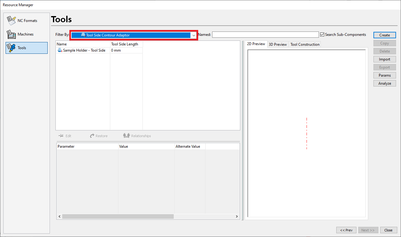
In the grid, select the tool side holder you want to create the profile for. In this example, it’s Sample_Holder_TS.
Click Edit. You see a black-and-yellow border around the holder parameters, indicating that you can edit them.
Use the Add, Delete, Insert, Fillet, Translate, and Scale buttons to create the profile.
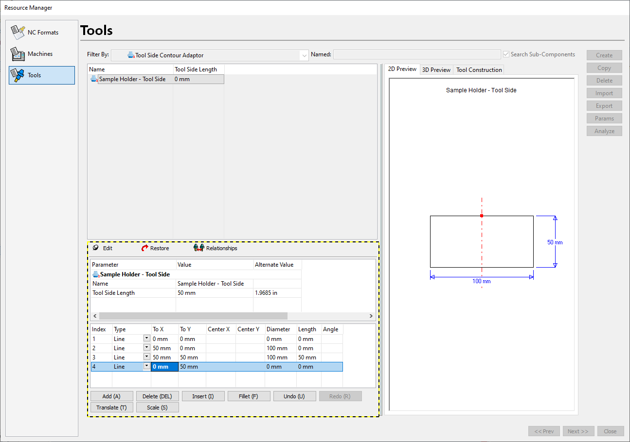
After you create the profile, click Edit to exit edit mode.
To view the holder assembly
After you create the machine and tool side for the holder, you can view the holder as a whole and apply adjustments.
In the Filter By drop-down menu, select Tool Holder.
In the grid, select the tool holder. In this example, it’s Sample_Holder.
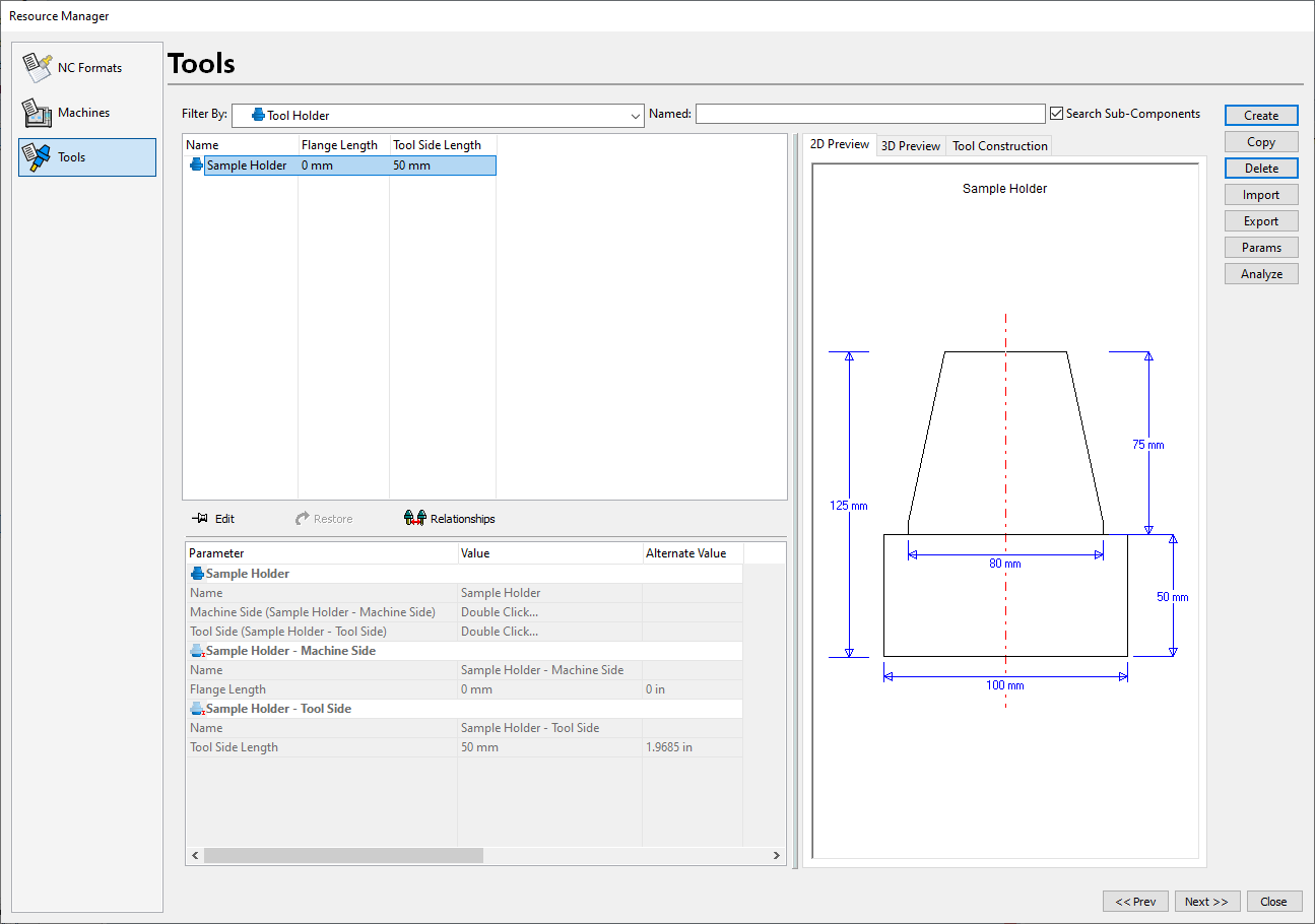
The tool holder is available here:
- In the Cutting Tool Manager when you create tool assemblies
- In the CAM wizard under the Click To Change column on the Cutting Tool page
- As the default holder in the machining setup
To create the cutter profile
To complete the tool assembly, define the contour cutter.
In the Filter By drop-down menu, select Contour Cutter.
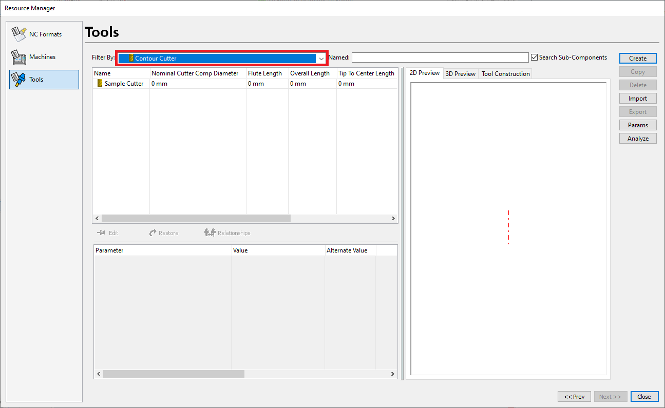
In the grid, select the tool side holder you want to create the profile for. In this example, it’s Sample_Cutter.
Click Edit. You see a black-and-yellow border around the holder parameters, indicating that you can edit them.
Use the Add, Delete, Insert, Fillet, Translate, and Scale buttons to create the profile.
Specify values for Flute Length and Nominal Cutter Comp Diameter for the tool.
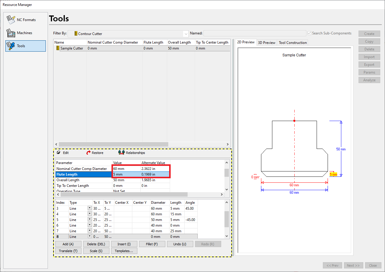
The 2D preview is updated as you create the profile. The last point on the profile closes it. In other words, X should be 0 on the last point of the profile.
After you create the profile, click Edit to exit edit mode.
To view the tool assembly
After you create the tool assembly, you can view it as a whole and apply adjustments.
In the Filter By drop down menu, select Tool Assembly.
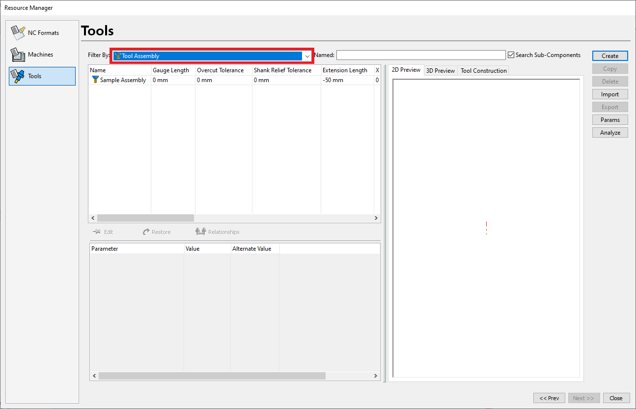
In the grid, select the tool assembly. In this example, it’s Sample_Assembly.
Click the Edit pin.
Double-click the Value column for Extension Length and specify a value.
Click the Edit pin again to apply the change.
After you create the tool assembly, it’s available for use in your TruePath projects.
To use the tool assembly
The tool assembly may replace another tool in the project through the Cutting Tools page in the CAM Import wizard or the CAM wizard.
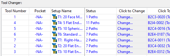
On the Cutting Tools page of the CAM Import Wizard or the CAM Wizard, find the tool you want to replace in the Tool Changer grid.
Select the Click To Change column in the grid.
Select the tool assembly you created.
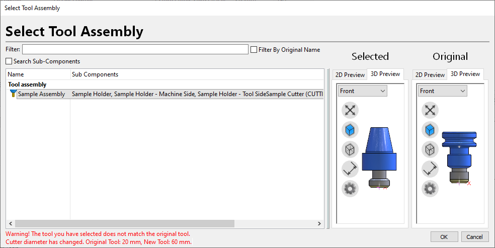
Click OK.
If you see a message that the tool dimensions don’t match those of the original tool, click OK to use the new tool assembly.
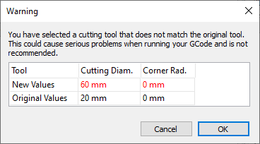
Click Finish.