
Use the Limit page to specify settings for limiting the area that you want to machine.
When creating a surface machining group in CAM mode, PartMaker creates a profile curve that is attached to that group. You can double-click on the curve to display the Curve Properties dialog, where you can specify to use the curve as a boundary curve.
Boundary
Limit — Select an option to define which part of the tool can touch the boundary:
 Limit tool center to boundary — The center of the tool cannot go outside the boundary.
 Limit tool periphery to boundary — The whole tool is contained within the boundary. The boundary is offset inwards by the tool radius.
Trimming — Select how to trim the toolpath to the Boundary curve.
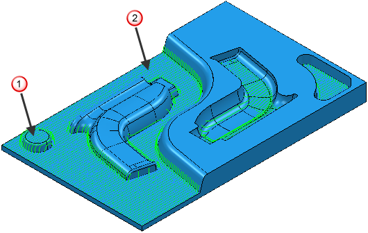
- Keep inside — When selected, it keeps the toolpath generated inside the boundary.
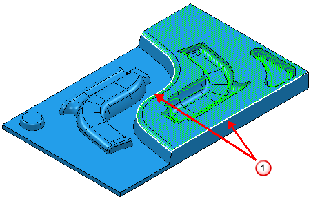
 Boundary
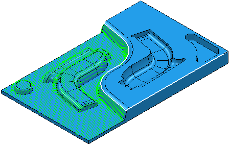
- Keep outside — When selected, it keeps the toolpath generated outside the boundary.
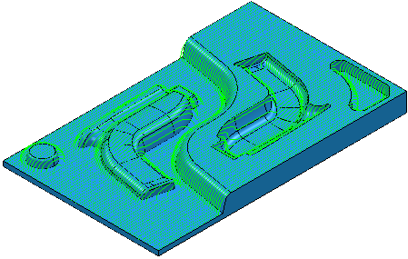
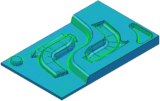
With no boundary selected, the toolpath is calculated over the whole model:
Block
Limit — Select an option to specify whether the tool is allowed outside the block.
 Allow tool center outside of block — The tool center can go outside the block. Select this option if the block represents the actual size of stock you are machining. This maximizes the removal of material during area clearance and avoids plunge or ramp entries wherever possible.
 Limit tool center to block edge — The tool center is limited to the block edge.
Z limits / X limits
Use these settings to limit the machining area by Z or X height depending on the machining function you are using. Specify maximum and minimum values to machine within a range.
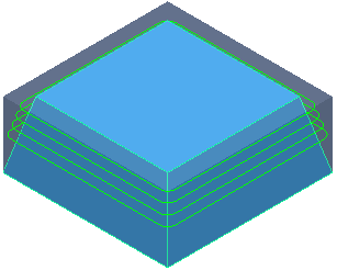
An unlimited toolpath:
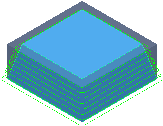
A toolpath limited in Z:
Z maximum
 Z minimum
- Maximum — Enter the maximum value. Cutting moves are always below this value.
- Minimum — Enter the minimum height in the field. Cutting moves are always above this value.