Use the Point distribution page to control how points are distributed along the cutting moves of a toolpath.
Output point distribution
Output type — Select the type of point distribution along the cutting moves.
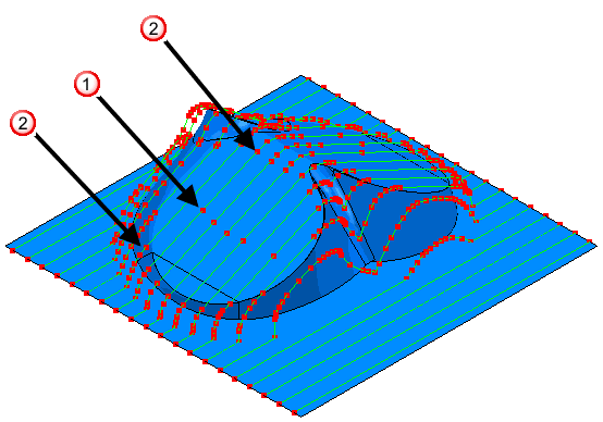
- Tolerance and keep arcs — Select to automatically remove unnecessary points in the toolpath while maintaining tolerance.
The points are not equispaced, as unnecessary points are deleted.
This option is not available when using the Mill Diam, Polar or Mill Cylinder machining functions, or for 4- and 5-axis simultaneous toolpaths.
- Tolerance and replace arcs — Select to replace arcs with straight line segments and to remove unnecessary points in the toolpath while maintaining tolerance. This is similar to
Tolerance and keep arcs except that all arcs are replaced by straight line segments (polylines). This option is suitable for machine tools that do not handle arcs well.
This option is not available when using the Mill Diam, Polar or Mill Cylinder machining functions, or for 4- and 5-axis simultaneous toolpaths.
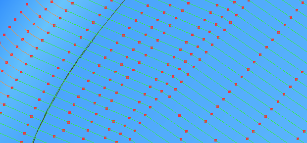
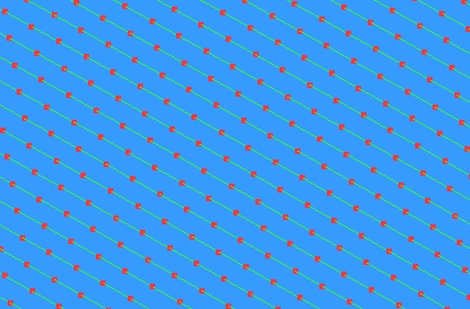
- Redistribute — Select to allow the insertion of new points. This ensures a constant distance between points, only inserting extra points if they are necessary to keep tolerance. This can be especially useful when selecting the
Point Separation distance, or
Point separation angle options. Redistribute
may increase toolpath-creation time, but reduce time on the machine tool. This option is suitable for machine tools that can handle large numbers of equispaced points.
- Fit arcs — Select to produce toolpaths with arcs inserted wherever possible. This option is suitable for machine tools that handle arcs well.
This option is not available when using the Mill Diam, Polar or Mill Cylinder machining functions, or for 4- and 5-axis simultaneous toolpaths.
 — Arc centres.
 — Arc ends.
Tolerance factor — Enter a value to determine how many points are removed. This must have a value between 0 (removes a minimum number of points) and 1 (removes a maximum number of points while maintaining tolerance, so the toolpath contains the minimum number of points).
Point separation distance — Select to limit the maximum distance between consecutive cutting move points.
Maximum distance — Enter the maximum distance between consecutive cutting move points.
Point separation angle — Select to limit the maximum change in angle between consecutive cutting move points.
Maximum angle — Enter the maximum angle between consecutive cutting move points. This is useful when approaching the gimbal lock position of your machine tool, where small angular changes can lead to large changes in the azimuth and elevation angles. To ensure the maximum angle is not exceeded, PartMaker adds additional toolpath points, which slow the machine tool.
A gimbal lock is a specific configuration of a multi-axis machine tool that occurs when the tool axis aligns with at least one rotary axis due to the position of one or more toolpath points. This configuration results in undesirable movements because, when close to the gimbal lock, small adjustments in the tool axis can require large changes in a rotary axis.
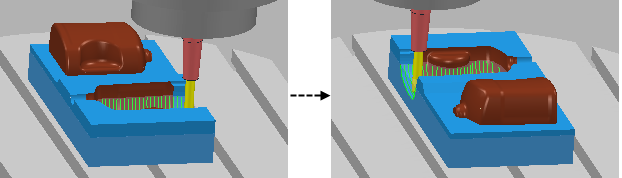
The graphic below shows the rotary axis of table-table machine tool (undesirably) rotating almost 180 in one second. This is because the machine tool machines a toolpath point at the bottom of the bottle cavity that coincides with the machine tool's gimbal lock.