
When creating solids models for use with Full Machine Simulation, follow these rules:
Machine Coordinate System
The Machine Coordinate System originates from:
- the face of the spindle/chuck face for PartMaker/Turn-Mill.
- the face of the guide bushing for PartMaker/SwissCAM.
The Z axis points out of the main spindle towards the sub-spindle.
Tool posts/spindles
For tool posts or spindles, the reference point must coincide with the Solid Model Coordinate System Origin (see Machine description for Full Machine Simulation for reference point positions for tool posts).
The orientation of the solid model relative to the three coordinate axes should be the same as its expected orientation in the Machine Coordinate System. The example below shows an XY turret that will perform a tool index about the Z-axis.
 Solid Model Coordinate System Origin
 Machine Coordinate System
End working slide tool post with sub-spindle attached
The tool post must be set as described above, with the exception that the zero point of the endworking slide must coincide with the attachment point of the sub-spindle on the slide (as opposed to the face of the sub-spindle).
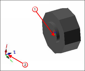
Holders
The holder can be defined in a different orientation than the Machine Coordinate system. This orientation will be rotated so the Holder to Tool Post Attachment Direction aligns with the Tool Post to Holder Attachment Direction. All holder data must be defined in the Holder Coordinate System.
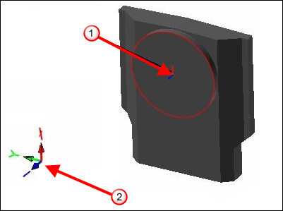
Components
The Component Reference Point must coincide with the Solid Model Coordinate System Origin. The orientation of the solid model relative to the three coordinate axes should be the same as its expected orientation in the Machine Coordinate System. If the End Working Slide and Back Working Slides are shared, the components belonging to these slides should be placed with the End Working Slide. If the Gang Slides are locked, the components belonging to these slides should be placed with Gang #1.
Sub-spindle components for Bar-Fed Mill machines
The model origin of the first component attached to the sub-spindle component must be the pivot point of the sub-spindle when the Defined by Model Origin of Sub-Spindle Component #1 option is selected on the Sub-Spindle Rotation Options dialog.
The components must also be modeled to the orientation of the sub-spindle when it is in its home orientation.
Sub-spindle components for B-axis enabled turrets
The components must be modeled to the orientation of the turret when it is in its home orientation for B-axis turrets.