
Using PartMaker you can assemble solid models into Swiss-type lathes and Turn-Mill centers and then use these assemblies to simulate the process of cutting a part.
This topic describes some of the concepts used in the process of constructing machine assemblies.
Machine Components
Machine components are the tool posts and spindles available for a particular machine. Machine components can, in turn, have other components attached to them, which are managed using the Components dialog.
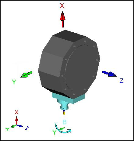
Motion Axes
Motion axes are defined in the Machine Data dialog for each machine component. They specify the directions in which a machine component can move. Enabling the X, Y, or Z motion axis allows the machine component to move in that axis during simulation. The B-axis applicable to the tool head and turrets allows the machine component to rotate about the Y-axis. The B-axis applicable to the gang allows a rotary attachment to rotate about the X or the Y axis (as specified on the Rotary Attachment dialog).
Travel Limits
Travel limits specify the limiting coordinates of the machine, beyond which the reference point of the machine component cannot travel. PartMaker checks that the reference point of the machine component is contained within the region bounded by the travel limits.
The availability of the travel limits depends on the motion axis of each machine component.
There are three ways to define travel limits:
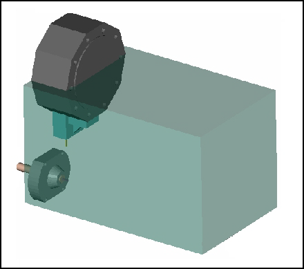
- If the machine component can
move in three axes: X, Y, and Z, the travel limits are defined as a box:
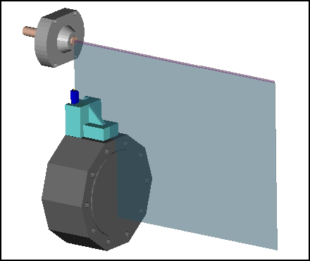
- If the machine component can
move in two axes (for example in XZ), the travel limits are defined as a plane:
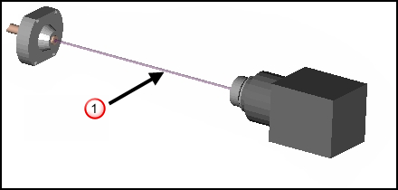
- If the machine component can
move in one axis
(for example in Z), the travel limits are defined as a line (
 ):
):
Reference Point
The reference point of the machine component specifies the point which is used for positioning of the machine component in Full Machine Simulation. The reference point is also used for checking overtravel by the machine component. The reference point is shown as a yellow dot in the following dialogs:
Multiple Tool Stations
A holder must be supplied with multiple stations on it and applied to those tools in the database in the Tool Assembly dialog. These tools are placed on the holder when Full Machine Simulation starts.