
Creating Break Points in Node Connections
Instead of using the default straight line connections between nodes, you can add Elbow nodes to reshape the node connections. Elbow node connections can be useful to clean up the schematic view, and avoid links crossing each other.
There are many benefits to using Elbow nodes in your schematic:
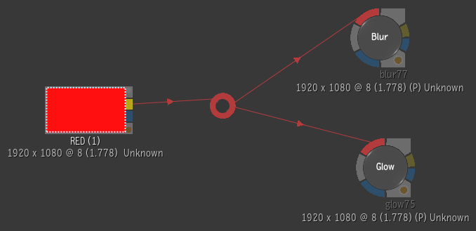
You can create multiple outgoing links from an Elbow node to other nodes in your schematic.
The Elbow node inherits the colour of its link. It turns red, if connected to a Front input, blue, if connected to a Matte input and grey when connected to Back input or when connected to multiple inputs.
An Elbow can be explicitly selected. This means that it is possible to move Elbow nodes along with the other nodes within a selection, and that you can move Elbow nodes independently of its parent and child nodes.
Note: Break Link points are automatically converted into Elbow nodes when an older setup is loaded.
Adding an Elbow Node to the Schematic
An Elbow node can be added to the Schematic in the following manners:
- By enabling the Add Points Edit mode and clicking on a link to add an Elbow node.
- By holding down the Add Points shortcut (A) to add elbow nodes and then letting go of the shortcut to return to the previously selected Edit mode.