The first stage removed the level control for pump KCH2PMP, as a result of which the level in reservoir CRES2 dropped steadily during the simulation. This stage adds a UPC scenario to control the pump again, switching it on when the level in the reservoir drops to 3.96 m and off when the level reaches 4.12 m. The scenario consists of a series of rules that define levels at which action is to be taken and the results of the action.
To set up the UPC scenario:
- Open the 'Network UPC' network. You must have a network open in order to create or edit a UPC scenario.
- Right-click the UPC group and choose New | UPC Scenario. Name the scenario 'CRES2 Pump Control' and click OK.
- Open the scenario:
- Right-click CRES2 Pump Control and select
Open (or drag the icon onto the window background). The UPC dialog is displayed.

- Type a description of the scenario in the box on the right and click
Update.

- Right-click CRES2 Pump Control and select
Open (or drag the icon onto the window background). The UPC dialog is displayed.
- Add the pump as a regulator in the scenario:
- Right-click the Global item on the left of the dialog and select Insert regulator.
- From the list of potential regulators, choose KCH2PMP.KCH20001.1.
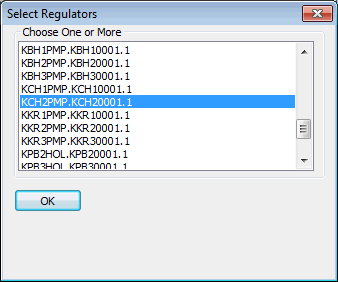
- The pump is added to the list on the left of the dialog. Drag the boundaries between the column headers so that you can see the full details in the item list.

- Add ranges to specify the object that is to be associated with the regulator and the levels at which action will be taken:
- Right-click the KCH2PMP item and select
Insert dependent | Range. The new range is added below the pump (expand the list to see it) and its details can be inserted in the right-hand pane.
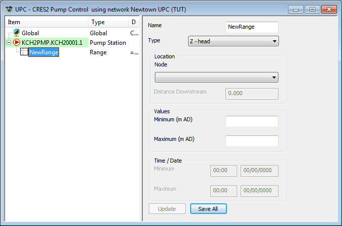
- Enter a
Name of 'LowLevel' and
Type of 'P - pressure', select CRES2 as the
Node and enter a value of 3.96 m as the
Maximum.
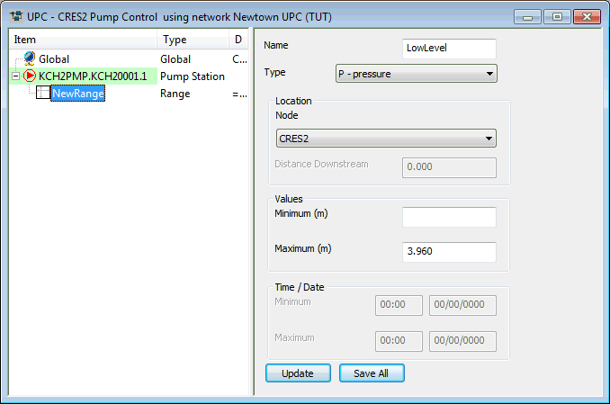
- Click Update. The entry on the left is updated with the new details. You can change the size of the UPC dialog by dragging its edges.
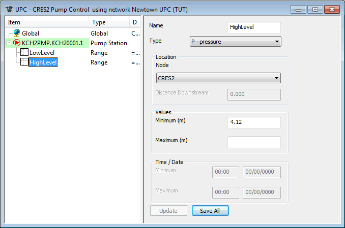
- Right-click the KCH2PMP item again and add a second range (Insert dependent | Range). Give this a
Name of 'HighLevel',
Type 'P - pressure',
Node CRES2 and
Minimum of 4.12 m. Click
Update.
The Description field for the range contains the details that were specified; this is generated by the system. You can view the full description by placing the mouse pointer over it; alternatively, drag the divider between the two panes to make the left-hand pane wider.
- Right-click the KCH2PMP item and select
Insert dependent | Range. The new range is added below the pump (expand the list to see it) and its details can be inserted in the right-hand pane.
- Add the rules for the scenario:
- Right-click the KCH2PMP item and select Insert dependent | Rule.
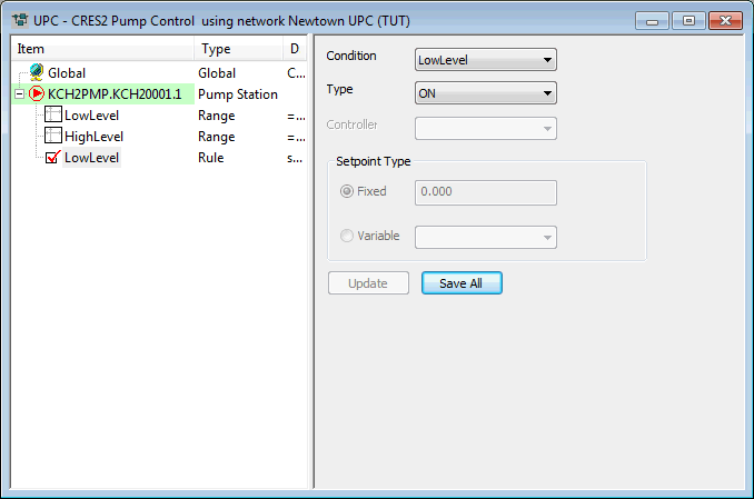
- For the Condition, select LowLevel from the drop-down list.
- For the Type, select ON. This rule specifies that when the LowLevel condition is satisfied, the regulator (KCH2PMP) is switched on. The LowLevel condition is satisfied when the level in the reservoir is on or below 3.96 m.
- Click
Update.
- Add a second rule with
Condition HighLevel and Type OFF.
This rule specifies that when the level in the reservoir is on or above 4.12 m the pump is switched off.
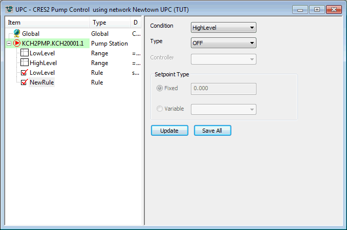
- Click Update.
- Click the UPC dialog's
 (Close dialog) button to close the dialog and click
Yes to save the changes. Close the GeoPlan view.
- Run the simulation with the UPC Scenario:
- Open the 'KCH2PMP Off' run.
- In the Run Title box, change the title to 'Regulate CRES2'.
- Drag the 'CRES2 Pump Control' icon into the UPC Scenario box.
- Click Run Simulations.
- When the simulation is complete, close the Output window.
- View the simulation results:
- Open the simulation from the 'Regulate CRES2' run.
- Use the
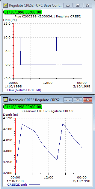
 (Graph) button to display a graph of flow for K200236.K200034.1 and depth for CRES2.
- Minimise the GeoPlan.
- Tile the views horizontally.
The graphs show that the pump is switched on and off when the level in the reservoir reaches the specified levels, in a similar way to the original level control.
- Close the GeoPlan and graph views.
The next stage modifies the UPC scenario to take account of electricity charges.
 Back to flowchartUPC Example
Editing a UPC scenario

