
Flatness
Typically, Flatness is a concern for a portion of the part, such as a sealing surface, an assembly plane.
To easily interpret Flatness, the area of interest must be isolated by using layers or a path plot. Typically a coordinate system is set up so the out of plane direction is the Z-direction. Setting the direction is done with an anchor system or a local coordinate system.
In the figure below, the sealing surface is in the XY plane, and is a very small fraction of the Z-deflection. Isolating the sealing surface to a layer helps in the interpretation.
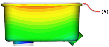
where A = Sealing Surface
If isolating the sealing surface is just above the tolerance, there is a possibility that the sealing surface is flat within tolerance but the surface is not in the XY plane. A command called flatness can be used to check a plane for flatness.
To use the flatness script:
- Select nodes on the plane to check, by any means necessary.
- Click
 (View tab > Windows panel > User Interface > Command line).
 - Type flatness on the command line. A message box will appear indicating the flatness before and after the warpage.