
Options and parameters explained
Jump to:
- Context view: Cut plane information
- Context menu: Cut plane alignment commands
- Cutting options
- Pins: Cylinder
- Pins: Hook
- Tongue and groove
Context view: Cut plane information
| Base point |
Reports the coordinates of the center point of the plane |
|
| Move parallel |
Translates the plane by a specified distance so that it remains parallel to the current orientation |
|
| Roll, Pitch, Yaw |
Reports the roll, pitch, and yaw angles of the plane Drag the slider or type an angle value to adjust the orientation of the plane. Roll and Pitch control the rotation of the cutting plane. Yaw sets the rotation of the plane around the vertical axis running through its center point. Note: With a yaw of 90°, the side edges are rotated as well, although no apparent change is seen. The angles of roll and pitch are exchanged, compared to a yaw of 0°.
|
|
| Size |
Reports the current size of the plane. Can be overwritten with manually typed values to adjust the size of the cut. |
Context menu: Cut plane alignment commands
These commands are accessed through right-clicking the part surface in the 3D view:
 Move basepoint here
|
Moves the basepoint of the plane to the clicked location. The plane remains parallel to its previous orientation. |
|
 Move plane parallel here
|
Moves the plane in a parallel fashion to the clicked location. The plane remains parallel and to its previous orientation. |
|
 Align plane parallel to this face
|
Rotates the plane so that it is parallel to the clicked face |
|
 Align plane vertical to this edge
|
Rotates the plane so that it is vertical to the selected edge |
Cutting options
These options appear in the context view and control the outcome of cutting.
| Only selected parts |
Cuts only selected parts even when the plane or stencil goes through other parts as well |
|
| Use plane boundary |
Cuts parts only to the extent of the plane boundary, otherwise cuts parts all the way across their bounding boxes regardless of the cut plane's indicated size. |
|
| Stitch parts |
Connects open triangle edges |
|
| Pins |
Generates pins and matching holes on the cut structures. These surface features are configurable. |
|
| Tonge and groove |
Generates a single step along the circumference of the cutting area |
|
| Remove original parts |
Removes the original parts after the cutting operation |
|
| Close cutting area |
Generates triangles to close the holes that emerged as a result of the cut |
|
| Create group |
Puts segments from cutting into groups according to their part origin |
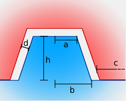
Pins: Cylinder
The cylinder-type pin is a cylindrical or conical stub.
| General settings | ||
|---|---|---|
| Height (h) |
Height of the pin above the surface |
|
| Pin spacing (c) |
Distance between pins |
|
| Min. border distance |
Minimum distance between the edges of the surface and the pins |
|
| Clearance (d) |
Distance between the pin and the hole |
| Cylinder settings | ||
|---|---|---|
| Holes on both sides |
Creates holes on both sides of the cut surface and no matching pins at all. Useful when separate pins or dowels are to be used later. |
|
| Top radius (a) |
Radius of the top surface of the cylinder |
|
| Bottom radius (b) |
Radius of the bottom surface of the cylinder |
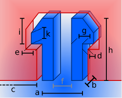
Pins: Hook
The hook-type pin is a pair of hooks that engages with a hole of matching contour and is, ideally, inseparable without destroying the hooks.
| General settings | ||
|---|---|---|
| Height (h) |
Height of the hook above the surface |
|
| Pin spacing (c) |
Distance between hook pairs |
|
| Min. border distance |
Minimum distance between the edges of the surface and the hook pairs |
|
| Clearance (d) |
Distance between the hook surface and the hole |
| Hook settings | ||
|---|---|---|
| Depth (b) |
Thickness of the hook perpendicular to the hook action |
|
| Width (a) |
Width of the hook structure without barb |
|
| Nose width (e) |
How far the hook's barb protrudes |
|
| Hook width (g) |
Thickness of the hook stem along the hook action |
|
| Spacing (f) |
Distance between hook stems |
|
| Nose height (i) |
Total height of the barb |
|
| Tip of nose height (k) |
Height of the barb's straight section |
Tongue and groove
Tongue and groove, normally a feature along boards and panels of straight shape, generates a single matching plug-and-socket arrangement of surface features that follows contours of the cut of arbitrary shape.
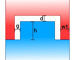
| Wall thickness (wt) |
Thickness of the rim |
|
| Gap (g) |
Peripheral clearance between the two parts, seen along the parallel to the cut |
|
| Height (h) |
Width of the nose |
|
| Distance (d) |
Axial clearance between the parts, seen along the perpendicular to the cut |
Tongue-and-groove features to reassemble sections after a cut