
Bars are individual support elements that connect two points, one on the part, the other on the platform, on other part surfaces, or even other bars themselves.
Jump to:
General parameters
| Parameter | Explanation | Notes |
|---|---|---|
| Bar contour |
Sets the cross section variant |
See Bar contour |
| Distance to part |
Distance between part and support. A negative value makes supports intrude into the part mesh. For example, can be used in conjunction with Angle at top to achieve a calculated contact patch. To calculate the appropriate value, use this simple trigonometric formula: Distance to part (negative) = (desired spot diameter - Width on end) * (Breaking point width - Width on end) / Height on end |
|
| Width on part |
Sets a separate contour width for (upper) bar ends that terminate on a part surface |
|
| Width on top-side part |
Sets a separate contour width for bar ends that terminate on a part surface at their lower end |
This is optional. To disable defining a separate width for the lower end of a bar, set this to -1. |
| Width on upper free anchor |
Bars where the upper anchors are not generated on part surface, or which are part of bouquets, are generated this wide at their upper end. For example, used for the individual bars in Adaptive bar lattices; otherwise has no effect. |
This is optional. To disable defining a separate width for the lower end of a bar, set this to -1. |
| Width on platform |
Contour width for bar ends that terminate on the build platform surface |
|
| Breaking point |
Generates a defined weak point near the upper part-connecting end of the bar |
See Breaking point |
| Right angle on part |
Sets whether bars should have a small curve to terminate in a right angle at the supported surface, rather than terminating at whatever angle they would otherwise do. |
|
| Smoothing distance |
Length of subdivisions that form the curve given by Distance to right angle. The shorter the subdivisions, the finer the curve is resolved, resulting in a smoother transition but also increased triangle count. |
|
| Junction shape |
Specifies how other bars, if there are any, transition into their respective parent bar |
|
| Pad on platform |
Generates a small plinth at the platform-terminating end of the bar |
See Pad on platform |
| Use density map |
Applies information provided by a 3D heatmap to lighten or strengthen structures locally |
Bar contour
| Bar contour | Notes | |
|---|---|---|
| Bar contour |
Style of cross-section for bars 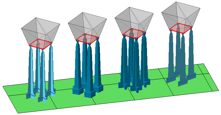 From left: Cross, solid bar, solid cross, hatch (open hatch tube not shown) Cross and Hatch have no enclosed volume, so their cross sections are rendered by single beam passes. This makes them fast to trace but also comparatively weak if used in larger sizes and lower numbers per area unit. Solid bar and Solid cross have enclosed volumes but require toolpathing for their interior, and in particular can produce intersections that can lead to multiple exposure if not merged properly. Open hatch tube is identical to Solid bar except that it is explicitly handled as open support by slicing. |
|
| Polygon corner |
Number of polygon corners for the solid bar. The more corners, the more rounded the bar's cross section becomes, but also the more triangles are generated. |
|
| Angle at top |
When set beyond
0, a pointy end is added to the normally blunt end that terminates parallel to the part surface.
Note: This point intrudes into the part mesh, so you may want to also work with
Distance to part, as well as with hatch cutting or subtraction during toolpathing, to mitigate overexposure at the intersection.
|
|
| Cross thickness |
The thickness of the contours for the solid cross |
|
| Radial type |
Generates solid bars with oval cross-sections. It aligns the oval cross-section by the semi-major axis with either X or Y axis, or radially away from the supported object's bounding box's center:
|
|
| Radial factor |
Used to generate solid bars with oval cross-sections. Makes them as wide as their thickness times this factor. |
|
| Hatch angle |
Direction of hatch-type bar support. A direction of 0° aligns the ribbon-like bars parallel to the Y axis, and higher values rotate this direction clockwise. |
|
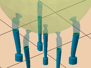
Breaking point
Generates a section where the bar locally constricts to form a defined weak point near the part surface, making it easier to remove supports from the part later on.
| Parameter | Explanation | Notes |
|---|---|---|
| Breaking point |
Toggles the generation of a constriction where bars would preferably break during removal |
|
| Breaking point width |
Diameter of constriction |
|
| Width on end |
Diameter of the bar past the breaking point where it attaches to the part surface |
|
| Breaking point height |
Length of the constriction itself |
|
| Height on start |
Length over which the bar thickness transitions into the constriction as seen from the bar's body |
|
| Height on end |
Length over which the bar thickness transitions out of the constriction towards the part surface |
Right angle on part
| Parameter | Explanation | Notes |
|---|---|---|
| Right angle on part |
Toggles generation of curve to meet the part surface more vertically locally, rather than terminating at whatever angle they arrive |
|
| Distance to right angle |
Distance away from the supported surface after which the bar should start to curve towards the direction the bar is coming from |
|
 Maximum connection angle
|
Limits the terminating angle that may be imposed on a bar by the supported surface to prevent generation of unprintable connections Caution: Compensation with a pointy tip (see
Angle at top) may be necessary to maintain contact patch size. However, this is not selective; all bars would receive this point. If this is of concern, split this action into two, one for critical support angles less or equal to the maximum connection angle and without point, and one for higher critical support angles and with point.
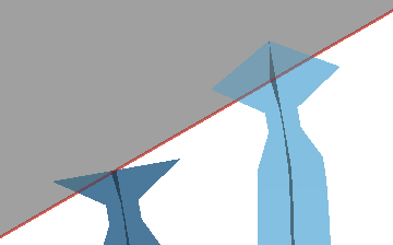 Maximum connection angle exceeded. Without point (left), with point (right). |
0° to 90° from the horizontal |
Pad on platform
A pad is a widened cross section at the platform end of a bar to reinforce adhesion to the platform surface
| Parameter | Explanation | Notes |
|---|---|---|
| Pad on platform |
Toggles pad generation |
|
| Pad width |
Pad diameter |
Excluding negative taper but including positive taper |
| Pad height |
Pad height, or vertical thickness |
Pads are only generated when the whole bar's Z length is at least 2.5 times the pad height. |
| Taper angle |
Adjusts either the side angle or the top angle for the pad depending on specified angle value 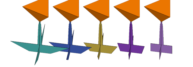 Series of negative angle values for pad taper. Left to right: -60° to 0° in 15° increments (Pad size exaggerated for illustration.) 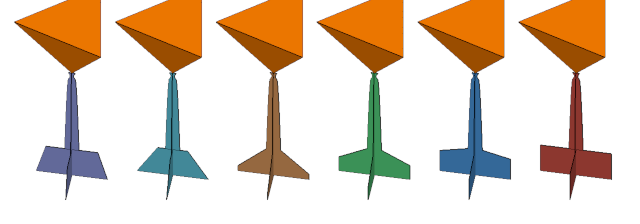 Series of positive angle values for pad taper. Left to right: 15° to 90° in 15° increments (Pad size exaggerated for illustration.) |
-60° to 90° |