
Activity 1: Find specific nets and components
In this activity, you find nets and components with different panel options in Schematic design. This allows you to quickly locate and review specific nets and components in the design.
Prerequisites
- Data file location: Electronics Samples > SmartMeter.
Steps
In the SmartMeter project, open the SmartMeter schematic design.
If necessary, Show Data Panel
 .
.Click Samples > Electronics Samples > Smart Meter to open the SmartMeter project design.
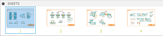
In the SmartMeter project, open the SmartMeter schematic design. You can see that it is spread across four sheets that show after expanding the SHEETS panel at the bottom of Schematic Workspace.
Specify settings to view Nets in Schematic.
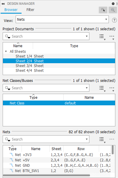
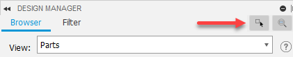
In the Design Manager panel, on Browser tab, in the View drop-down list, select Nets.
In Project Documents group, under All Sheets select Sheet 2/4.
In Net Classes/Busses group select Net Class default. List of nets is shown in the Nets group.
 Note: You can tidy up the workspace by docking panels to the edges of the design workspace. For this in the panel title bar, click the More menu and select Dock to right or Dock to left.
Click individual nets to see them highlighted in the schematic design.
Note: The Row and Column entries in the Nets list also indicate the net location by sheet grid row and column.Check the properties of selected Net.
Click Inspector panel at top-right edge of the design window.
In the Properties of Wires group you can see attributes of the selected net that can be changed.
In the Selected Objects group you can see the start (X1, Y1) and end points (X2, Y2) of the net.
Note: You can check these values by placing the pointer on the points of Net and see the values that show at the top of the Schematic design workspace.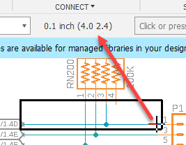
Change the properties of selected net.
In the Design Manager panel, in the Search box of Nets group, enter N$6 and select Net N$66.
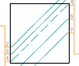
In the Inspector panel, under Properties of Wires group, change Style to longdash to clearly see this net.
See that this net diagonally crosses the selection frame on the canvas.
When finished, change the Style of N$66 back to continuous.
Review components using the filter.
In the Design Manager panel, click the Filter tab.
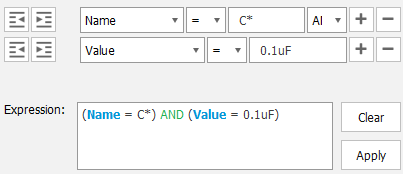
Set up a filter with Name = C* AND Value = 0.1uF.
Select Name from drop-down list.
Select = from the next drop-down list.
Enter C in the expression box.
Click Add icon
 to add new expression.
Select Value from drop-down list.
Select = from the next drop-down list.
Enter 0.1uF in the expression box.
See how this builds in the Expression field, and presents all filtered capacitors in the Results list.
In the Result list, click individual capacitors and see how they are highlighted in the schematic design.
Hold Shift+Click two or more capacitors to show a frame around the group on the canvas and their shared properties in the Inspector panel.
Show specific parts.
Check that both show controls: Select in Design and Zoom to selection are enabled in the Design Manager panel.
In the Design Manager panel, on the Browser tab, remain on Sheet 2/4 and switch the view to Components.
Choose a part to show, for example, J5 by clicking it in Components list.
Zoom out to see all or most of the Schematic design on the canvas.
Click Show tool
 , then on the command line, enter @ J5. The component shows as highlighted with a black frame on the canvas.
Activity 1 summary
In this activity, you used filters and search to find nets and components on the canvas in the Schematic design.