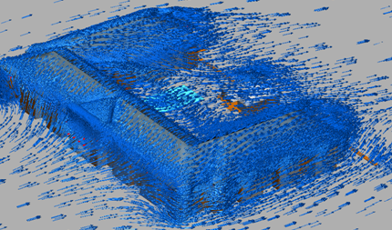
Wind loading analyses simulate the air flow and resultant structural loading on buildings, large signs, and other structures. Examples include:
Application Examples
Flow Over and around buildings
Wind Loading on windows, signs, lightboards, and façades
Modeling Strategy
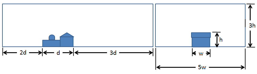
A volume surrounding the device must be constructed. In most cases the surrounding volume is an open environment:
- Add this volume either in the CAD model or in Autodesk Simulation CFD with the External Volume tool. (We recommend creating it in the CAD model so the volume can be coplanar with the ground-plane of the structure.)
- Build the environment geometry using these recommended relative dimensions:
- Simplify the geometry to remove extraneous features. Simplify or rebuild parts to remove detail that is not relevant to the simulation.
These items and several more are presented in detail in the AEC Geometry Modeling topic...
Materials
Assign Air to all air regions.
- The properties of air are constant for forced-flow models (fan or velocity-driven) that have minimal thermal stratification.
- If some (or all) of the air movement is due to natural convection (buoyancy), change the Environment setting to Variable. This allows the properties of air to vary with temperature, and for air movement to occur as a result of temperature gradients.
The default air properties are set for 68 °F. If the operating temperature is greater than 90 °F or less than 50 °F, modify the Scenario Environment temperature to the appropriate value. This ensures the air density is appropriate for the operating conditions.
Several other material types are commonly used in AEC applications:
- Solids
- Internal fans
- Distributed Resistances
Click here for more about materials in AEC applications...
Boundary Conditions
The boundary conditions for wind loading analyses are straightforward:
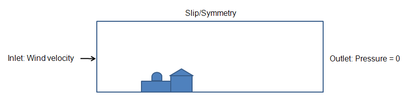
- To define the inlet of the air volume, assign the wind speed as a Velocity boundary condition.
- To define the outlet of the air volume, assign Static Gage Pressure = 0.
- If the air region simulates a free-space environment (not a wind-tunnel), assign Slip/Symmetry to the top and sides of the region. (Do not specify a condition on the ground plane, because the air does not physically move along the ground plane.)
Mesh
A basic guideline for a high-quality analysis model is that the mesh distribution be sufficient to resolve the flow and temperature gradients efficiently. In regions where the flow circulates or experiences large gradients (such as in wakes, vortices, and separation regions), a finer mesh is required.
For most models, use Automatic Sizing to define the mesh distribution. It may be necessary to locally refine the mesh on geometric features that are highly detailed. For more information about Mesh Autosizing and model preparation...
In some cases, it may be necessary to adjust the Minimum Refinement Length to reduce their effect on the overall mesh count.
To locally refine the mesh in high-gradient flow regions:
- Adjust the mesh distribution on geometric volumes and surfaces.
- If there are no appropriate geometric features in a particular region, create a mesh refinement region:
- Add one or more volumes in the CAD model.
- Create a Refinement Region from the Meshing task.
Running
On the Physics tab of the Solve dialog:
- Flow = On
- If solving for heat transfer:
- Heat Transfer = On
- Automatic Forced Convection = On (Do not enable this if the Material Environment setting is set to Variable.)
On the Control tab of the Solve dialog:
- Iterations to run = 750
The specified number of iterations, 750, is the maximum number of iterations that will run. (This has been found to be sufficient for most mechanical ventilation simulations.) Autodesk Simulation CFD stops the solution when either 750 iterations have been completed or when the solution reaches convergence, whichever comes first. If heat transfer and Automatic Forced Convection are enabled, Autodesk Simulation CFD automatically solves for the temperature distribution after the flow solution is complete.
- To simulate surface-to-surface radiation and solar heating, enable Radiation. Models with very high component temperatures or open fires (such as for smoke visibility) are good applications of radiation. To enable Radiation, check the Radiation box on the Physics tab. For more about Radiation...
- To simulate solar heating (either diurnal or steady-state), enable Radiation, and click the Solar heating button. Specify the time, date, location, and direction to define the solar analysis. For more about Solar heating...
- Once the box is checked, you can set up solar heating parameters (time, date, location, direction) in the “Solar Heating” dialog.
- To simulate mixing, especially for smoke analyses and chemical contaminant studies, enable the General Scalar solver. (Click the Advanced button on the Physics tab.) For more about Scalar Mixing...
- To simulate condensation of moist air, enable the Humidity solver. (Click the Advanced button on the Physics tab.) For more about Humidity...
- To compute the level of Thermal Comfort, click the Result quantities button on the Control tab, and check the Thermal comfort box. For more about Thermal Comfort...
- To compute the visibility through smoke, click the Result quantities button on the Control tab, and check the Smoke visibility box. For more about Smoke Visibility...
Additional Solver Capabilities
Results Extraction
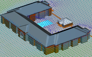
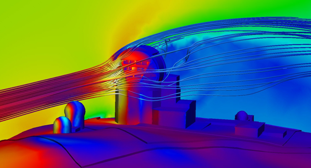
- Use Results Planes and Iso Surfaces to visualize the flow in and around the fixture.
- Use Particle traces to visualize air movement.
- Display temperature directly on parts and use Results Parts to extract quantitative temperature data.
- Use the Decision Center to compare results from multiple scenarios. Save summary images and create summary items, and evaluate the results in the Critical Values table.
For more general information, use the extensive collection of results visualization tools to extract flow and thermal results.