The Skin modifier is a skeletal deformation tool that lets you deform one object with another object. Mesh, patch, or NURBS objects can be deformed by bones, splines, and other objects.
When you apply the Skin modifier to a mesh and then assign bones within the modifier, each bone receives a capsule-shaped "envelope." Vertices of the modified object within these envelopes move with the bones. Where envelopes overlap, each vertex's motion is a blend of the motions of bones that affect the vertex. This is accomplished with weighting.
By default, each vertex that's affected by a single bone is given a Weight value of 1.0, which means the vertex responds only to that bone's motion. Vertices within the intersection of two bones' envelopes have two Weight values: one for each bone. And you can use Skin modifier toolsets such as the Weight Tool dialog to arbitrarily assign vertices to any number of bones.
The ratio of a vertex's Weight values, which always total 1.0, determine the relative extent to which each bone's motion affects the vertex. For example, if a vertex's weight with respect to bone 1 is 0.8 and its weight with respect to bone 2 is 0.2, then the motion of bone 1 will have four times greater influence on the vertex than will the motion of bone 2.
The initial envelope shape and position depends on the type of bone object. Bones create a linear envelope that extends along the longest axis of the bone geometry. Spline objects create envelopes that follow the curve of the spline. Primitive objects create an envelope that follows the longest axis of the object.
You can apply the Skin modifier to several objects at the same time.
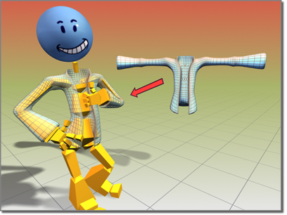
Jacket object deformed using the Skin modifier
In 3ds Max you can mirror envelope and vertex assignments from one side of the mesh to the other with commands on the Mirror Parameters rollout.
Angle Deformers
You can deform the skin mesh based on the angle of the bones. Three deformers that you add via the Gizmos rollout let you shape the mesh based on bone angles:
- The Joint Angle and Bulge Angle deformers use a lattice similar to an FFD lattice to shape the mesh at a specific angle.
- The Morph Angle deformer morphs the mesh at specified angles. You create morph targets with modifiers above the Skin modifier in the stack. Alternatively, you can create a copy of the mesh with the Snapshot tool, then deform the mesh with standard tools.
Procedures
To use the Skin modifier:
- Prepare the skin (mesh or patch object) and skeleton (bones, CAT or Biped skeletons, or other objects). Carefully
 place the skeleton inside the mesh or patch object so that its components are able to influence polygons or patches in their immediate vicinity. Tip: The skeleton can already be animated, or you can animate it after applying its components to the Skin modifier.
 -
 Select the mesh or patch object and apply the Skin modifier.
 - In the Parameters rollout, click Add and choose the skeleton objects.
- Turn on Edit Envelopes and select an envelope to modify the volume in which each bone can influence the surrounding geometry.
To weight vertices manually:
- Make sure Parameters rollout > Edit Envelopes is on, then turn on Vertices.
- On the mesh, select vertices to weight manually.
Each selected vertex is surrounded by a small white rectangle.
- In the list of bones on the Parameters rollout, highlight the name of the bone for which you want to change the vertex weights.
- In the Weight Properties group on the Parameters rollout, set the Abs. Effect value to the new vertex weight.
The Abs. Effect value is a decimal number between 0.0 and 1.0. The latter value means the vertex is controlled only by the highlighted bone. Values less than 1.0 means that other bones can also affect the vertex's motion.
The default method of using envelopes to determine which bones affect which mesh vertices can suffice for many situations, but if you need more control, you can opt to apply vertex weights explicitly.
To mirror envelope or vertex weight settings:
- Adjust envelopes and vertex weights on one side of the mesh.
- On the Mirror Parameters rollout, click Mirror Mode.
The mirror plane appears at the position and orientation of the mesh's pivot point.
- If the mirror plane is not at the center of the mesh, change the Mirror Offset parameter to move the plane to the center.
- If some vertices in the left or right side of the mesh are red rather than blue or green, increase the Mirror Thresh value until all vertices are blue or green.
- On the Mirror Parameters rollout, click the appropriate Paste button to paste green or blue envelopes or vertex weights to the other side of the mesh.
To adjust the skin and/or bones without affecting the envelopes:
-
 Save the scene.
 This is a potentially destructive operation, so it's best not to take any chances with your data.
-
 Select the object to which the Skin modifier is applied.
 - On the Advanced Parameters rollout, turn off Always Deform.
- Apply any necessary transforms to the mesh/patch object or bones objects.
- Turn Always Deform back on.
To adjust the bones only, you can also use skin pose.
Example: To apply the Skin modifier to a cylinder with a bones skeleton:
- On the
 Create panel, with
  (Geometry) active, under Standard Primitives, click Cylinder.
 - In the middle of the Top viewport, click and drag 20 units to create the base of the cylinder.
- Release the mouse button and drag up 130 units to establish the height of the cylinder.
- On the parameters rollout, set Height Segments to 20.
This provides mesh detail for a smooth surface deformation.
- On the
 Create panel, click
  (Systems). On the Object Type rollout, click Bones.
 Make sure an IK Solver is chosen in the IK Solver list. Turn on Assign To Children. (This should turn on Assign To Root as well.)
- In the Front viewport, click successively three times: below the cylinder, in the middle of the cylinder, and above the top of the cylinder.
- Right-click to end Bones creation.
Three bones display. Two of them are within the middle of the cylinder.
-
 Select the cylinder.
 - On the
 Modify panel
  Modifier List, choose Skin.
 - On the Skin modifier Parameters rollout, click Add, and use the Select Bones dialog to select the three bones.
The names of the bones are now displayed in the list.
- In the Front viewport,
 select the bone end effector (IK Chain01) and move it around.
 The cylinder deforms to follow the bones. To adjust envelopes to refine the surface deformation, choose the Skin modifier's Envelope sub-object level, and use the Edit Envelopes controls to resize envelopes and change vertex weights.
 Example: To use dual-quaternion (DQ) skinning:
- Make sure the joint where you'll apply DQ skinning uses blended weighting between the two adjacent bones. One way to do this is by increasing the diameters of the envelope capsules at the joint so they overlap.
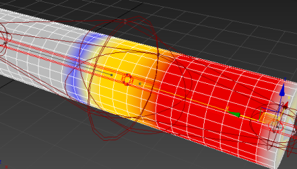
The yellow area shows where the vertex weighting is shared between the neighboring bones.
- Rotate the "driver" bone about its longest axis so that the resulting loss of volume is readily apparent. Then undo the rotation.
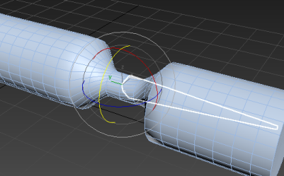
Mesh constriction caused by rotating the "driver" bone about its long axis
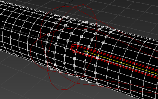
- Select the mesh object, go to the Envelope sub-object level, turn on Vertices, and select the vertices at the joint.
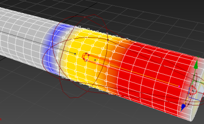
Selected vertices within overlapping envelopes volume
- In the Dual Quaternion group on the Parameters rollout, make sure DQ Skinning Toggle is on, as it is by default, and then turn on Blend Weights.

This turns the mesh black in shaded viewports and allows you to use all vertex-weighting tools except Weight Table to apply a DQ mask instead. In this example, you'll use the Weight Tool dialog, but you can use whichever tools for setting weights you're most comfortable with.
- In the Weight Properties group, click
 (Weight Tool) to open the Weight Tool dialog.
 - On the dialog, click the 1 button, at the right end of the second row.
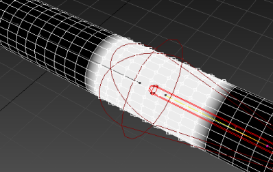
This sets the highest possible DQ blending value for all selected vertices, as depicted in the mesh with white geometry.
- Also on the dialog, click the Blend button several times. It's located at the right end of the bottom row of buttons.
This smooths the transition between the weighted vertices and their neighbors.
- Close the Weight Tool dialog, then turn off Blend Weights on the Parameters rollout.
The mesh's appearance returns to normal.
- Rotate the driver bone again about its long axis.
This time the loss of volume resulting from the twisting motion is significantly reduced.
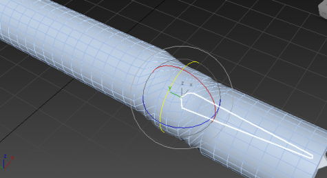
By default, the Skin modifier uses linear weighting, which works fine in most cases when deforming a character mesh with a skeleton. However, if a bone twists about its longest axis, the skin mesh tends to collapse, causing an unsightly loss of volume. In such cases you can apply dual-quaternion skinning, which prevents the loss of volume.
Example: To use a morph angle deformer:
- At frame 50, animate bone 2 so that bones 1 and 2 represent a 90-degree angle.
- At frame 0, the bones should be straight at about a 180-degree angle.
- Go to frame 0.
- In the Parameters rollout, turn on Edit Envelopes.
- Select the child bone (bone 2) in the modifier's list of bones.
- In the Select group, turn on Vertices.
This allows you to select vertices.
- In the viewports,
 region-select a good portion of the vertices that are controlled by both bones.
 - In the Gizmos rollout, select the Morph Angle Deformer in the drop-down list, and then click Add Gizmo.
The Deformer Parameters rollout displays. A base morph target is the first and only target in the list.
Tip: if the Deformer doesn't assign, make sure that bone 2 and not bone 1 is selected in the list. - Scrub the Time Slider to frame 50.
- Add an Edit Mesh modifier above the Skin modifier on the modifier stack.
- In the Edit Mesh modifier, turn on Vertex and Soft Selection.
- Edit the mesh to the shape you want.
- In the stack, go back down to the Skin modifier. If 3ds Max displays the topology warning dialog, click Yes.
- In the Deformer Parameters rollout, click Add From Stack.
A new morph target is added at about 90 degrees.
- Delete the Edit Mesh modifier from the stack.
There is a doubling effect of the morph if you don’t delete or deactivate the Edit Mesh modifier.
- Scrub the time slider. The mesh morphs as the bone angle changes.
Create the cylinder and bones from the preceding procedure before you continue with this procedure.
Interface
Modifier Stack
- Envelope
-
Access this sub-object level to modify envelopes and vertex weights.
Tip: You can use the quad menu (right-click) to choose this sub-object level.
Quad Menu
A number of Skin modifier commands are available from the quad menu on the Tools 1 and Tools 2 quadrants:

Rollouts
The Skin modifier has several rollouts. These are described in the topics that follow.