You can specify the model to use each time you insert a feature or you can specify the default models to use for all new overhead and underground features. Default models apply to all design layout features regardless of the method you use to insert them (ribbon, Design Explorer, or command line). In addition, you can specify the default voltage for primary and secondary conductors and the status for all new features.
- Click Home tab
 Electric Underground or Electric Overhead paneldown arrow to display the default models palette.
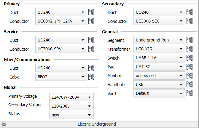
- Set any of the following defaults:
- For Electric Underground, specify default models to use for primary, secondary, and service ducts and conductors, and for segments, transformers, switches, pads, manholes, handholes, and vaults.
- For Electric Overhead, specify default models to use for primary, secondary, and service conductors, poles, and pole heads, lights, and transformers, and neutral lines.
For more information about specifying default neutral models, see To Specify a Neutral Model.
Use Create Equal Spans and Preferred Span Length to specify the distance to insert poles automatically in overhead design. For more information, see To Set Equal Overhead Spans and Define Span Length.
If you are using the Communications industry model, you can also set defaults for Fiber/Communications ducts and cables for both underground and overhead design.
- To specify default voltage for primary and secondary conductors and the status for all new features, use Primary Voltage, Secondary Voltage, and Status in the Global area.