- To set Primary and Secondary voltage for new conductors, and Status for all new features, click Home tab
 Electric Overhead paneldown arrow to display the defaults palette for overhead design features.
 - In the Global area, set Primary Voltage, Secondary Voltage, and Status.
For more information, see To Set Voltage and Status for New Features.
- Set any other desired defaults.
For more information on the defaults palette, see To Specify Default Models.
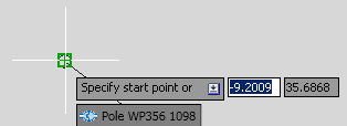
- Click Home tabElectric Underground panel and use the tools to create overhead lines, poles, devices, structures, and guys.
If the features you want to create are not available on the Electric Overhead panel, use the Feature Library or Model Viewer in the Design Explorer. For more information, see About the Feature Library and About the Model Viewer.
Note: As you create features, be sure to maintain connectivity to avoid validation issues. The Connected To icon helps identify features for connection.
For more information, see About Connection.
Conductor attachment points are determined by the 3D Model of the pole head.
As you create features, the Validation Results palette displays validation information such as sag and guying. For more information, see About Design Validation.