Set a vertex level on a feature line, survey figure, plot line, or 3D polyline at a given gradient/slope from a specified location.
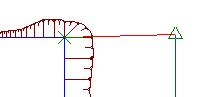
Example: Specify the level of a ditch footprint in relation to a building pad level. Temporary graphics show the reference point and the vertices on the feature line.
- Click
 Find.
Find.
- Select the reference point to use.
The level of the selected point is displayed at the command line.
- Select the feature line or other object to which you want to apply the level.
Temporary graphics are drawn on-screen to show the reference point and the vertices and level points on the feature line.
- Do one of the following:
- Click to select the first point selected on the feature line. Or move your mouse to snap to a different point on the feature line, and then click to select it.
- Enter Insert and then select a point on the feature line at which to insert a new level point. On 3D polylines, a new IP is inserted.
The distance between the selected point and the reference point, and the level and gradient of the selected point, are displayed at the command line.
- Do one of the following:
- Enter a gradient. The gradient is applied between the reference point and the point on the feature line.
- Enter Slope and then enter a slope. The slope is applied between the reference point and the point on the feature line.
- Enter Difference and enter the level difference. The level difference is applied between the reference point and the point on the feature line.
The assigned level for the point is displayed at the command line.
- The original reference point remains active. Select another feature line to continue setting levels in reference to this point. Or, press Enter to end the command.