An quickstart guide on how to use Autodesk Netfabb Local Simulation and where to get more information.
Jump to:
- How to set up a part-scale powderbed-fusion simulation
- How to set up a directed-energy deposition simulation
- Further reading
How to set up a part-scale powderbed-fusion simulation
Tip: To review and adjust the
Simulation settings, choose
.
- Create a new simulation project by choosing .
- In the simulation type selection, choose Powder bed, then click Create simulation.
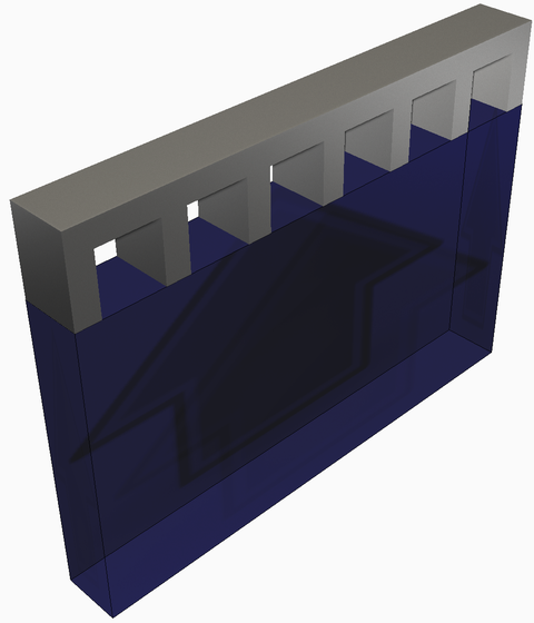
- This prompts you to
import 3D geometric files for which to simulate the additive process. For each file you load, you have the opportunity to select whether it's part or support, and in particular for the latter how to treat it, either take it as-is or simplify it to its envelope with a fraction of the actual material's solidity.
- In the
process parameter (PRM) file library, identify a set of matching processing parameters and material of the part to be simulated, or create a new custom PRM file if none, or no suitable one, currently exists.
Note: A license of Local Simulation is required to generate new PRM files.
- Optionally, adjust the orientation of the part by right-clicking on its entry in the Browser and selecting Move.
- In the Machine dialog specify again the processing parameters for the build, either the entire build or, optionally, separate ones for the individual components.
- Use the Build Plate panel to adjust the build plate material, size, build plate heating, and mechanical constraints.
- In the Operating Conditions dialog, choose the ambient temperature and thermal boundary conditions during processing.
- Optionally, use the Heat Treatment panel to detail the time-temperature values of a stress relief heat treatment cycle, if one is used.
- Select mesh settings appropriate for the size and complexity of the component.
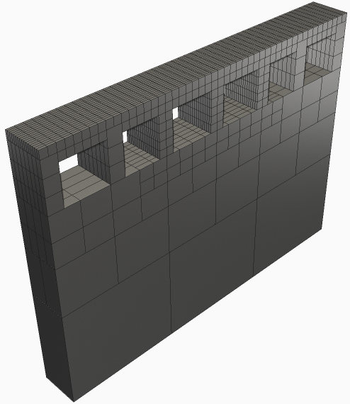
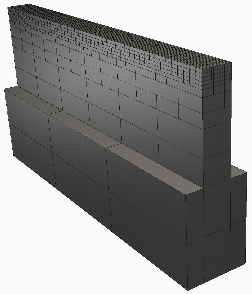
- Generate a
Mesh Preview to ensure adequate voxel representation of the source geometry and to check for flaws in the mesh that could affect simulation results.
- Solve the simulation.
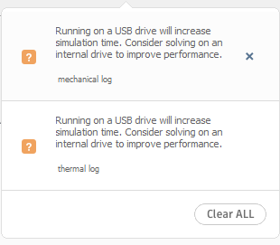
- Check any notifications in the top right of the screen as they appear, or
review the log files for errors or warnings.
- Examine model results.
How to set up a directed-energy deposition simulation
Note: Simulation Utility cannot run directed-energy deposition (DED) simulations. These require the full
Local Simulation product.
- Create a new simulation project by choosing .
- In the simulation type selection, choose Directed energy deposition, then click Create simulation.
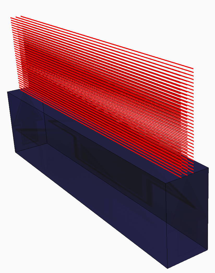
- You are now prompted to open
a laser vector (LSR) file. An LSR file specifies the power, speed, laser spot size, beginning and end points, and timing of the laser vectors to build a DED component.
- Specify the material and absorption efficiency on the Machine panel. Laser-based DED systems absorption efficiencies are generally in the range of 30-40%. Electron beam systems typically have much higher absorption efficiencies, between 88-98%.
- In the Build Plate dialog, specify the size, build plate heating, and mechanical constraints.
- In the Operating Conditions dialog, choose the ambient temperature and global convection coefficient during processing.
- Select mesh settings appropriate for the size and complexity of the component.
- Generate a mesh preview to ensure adequate voxel representation of the source geometry and to check for flaws in the mesh that could affect simulation results.
- Solve the simulation.
- Check any notifications in the top right of the screen as they appear, or
review the log files for errors or warnings.
- Examine model results.
Further reading
See the Tutorials in the Help for videos and step-by-step walkthroughs of simulation solutions, using sample files that you can download from an Autodesk website.