View the results from a Process Simulation study
This feature is part of an extension. Extensions are a flexible way to access additional capabilities in Fusion. Learn more.
After solving the Process Simulation study, view and analyze the simulated results.
If the Results contextual environment is not open:
In the Browser, ensure that the Process Simulation study whose results you want to view is active.
On the Manufacture workspace toolbar, click Additive > Process Simulation > Results View
 .
.The Results contextual environment opens and shows the mesh of the part colored according to the active results type.
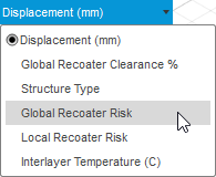
On the canvas, next to the color legend, select what type of results you want to view:

If you are viewing Displacement, Structure Type, Local Recoater Risk, or Interlayer Temperature, use the controls at the bottom of the canvas to play through the simulation.

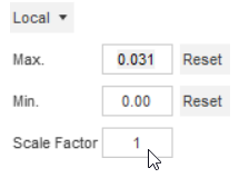
If you are viewing Displacement or Interlayer Temperature, enter a Scale Factor between 0 and 100 for the visual warpage.

The default value of 1 shows expected warpage; a value of 0 removes all warpage; a value greater than 1 shows exaggerated warpage.

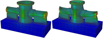
Exaggerated warpage using a scale factor of 10 (left) and 50 (right).
Tip: Change the Magnitude to show only the X, Y, or Z component of the displacement. Switch between Local and Global to alter the range of the color legend.Optional steps:
To switch between showing, and not showing, the edges of mesh elements in the simulated results, click Edit > Toggle Element Edges
 .
.To switch between showing, and not showing, the minimum and maximum locations for the currently selected result, click Edit > Toggle Min/Max Probes
 .
.To open the folder location where the results files from the Process Simulation study are stored, click Edit > Open Results Folder
 .
.To add a mesh body to the manufacturing model that automatically compensates for the displacement predicted by the Process Simulation study, click Edit > Create Compensated Mesh Body
 .
.To export an STL file that automatically compensates for the displacement predicted by the Process Simulation study, click Actions > Export Compensated STL
 .
.To export an STL file of the warped part as predicted by the Process Simulation study, click Actions > Export Warped STL
 .
.To export a displacement color-coded 3MF file of the warped part as predicted by the Process Simulation study, click Actions > Export Color 3MF
 .
.
Click Finish Results
 to close the contextual environment.