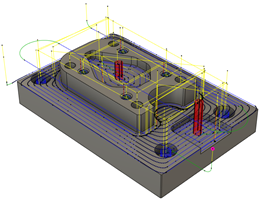
Display toolpaths during simulation
In the Browser, select the setup or the individual operations you want to simulate.
Tip: Hold theCtrlkey to multiselect operations.On the Manufacture workspace toolbar, click Actions > Simulate with Machine
 or Actions > Simulate
  .
.A dialog is displayed, and the Simulation contextual environment opens, replacing all the tabs in the Manufacture workspace.
If the toolpaths are not displayed, on the Simulation contextual environment’s toolbar, click Display > Toolpaths
 .
.
(Optional) Use the options in the dialog to further control the visibility of the toolpaths:
- To show link moves, which occur between cutting moves, select the Show Links checkbox.
- To show lead moves, which are the entry to and exit from cutting moves, select the Show Leads checkbox.
- To show cutting moves, probing moves, and additive DED moves, select the Show Cutting Moves checkbox.
- To show points in toolpaths, which indicate where each move starts and ends, select the Show Points checkbox.
- To show connection moves between operations, select the Show Connections checkbox.
- To determine which sections and order of the toolpaths are displayed, choose a Mode option.
Use the player controls and timeline to navigate the simulation.
Use the other options on the toolbar and in the dialog to control the visibility of the tool, machine, and stock during the simulation, and to check for simulation issues and to view the NC code.