Configurable aspects
A Configurable Aspect is any parameter, state, selection, theme, or property that you can add to the Configuration Table to define the differences between Configurations in a design.
You can configure the following aspects of a Configured Design in Fusion:
- User Parameters
- Feature Parameters
- Other Feature Aspects
- Suppression
- Visibility
- Physical Material
- Appearance
- Sheet Metal Rules
- Plastic Rules
- Properties
In Configuration Mode, you can click highlighted Features in the Timeline and objects in the Browser to display a list of configurable aspects for that feature or object. Then you can check aspects to add them to the Configuration Table as columns.
User Parameters
You can configure User Parameters to drive key aspects of your design.
For example, you can configure length, width, and height to create different sizes of a design.
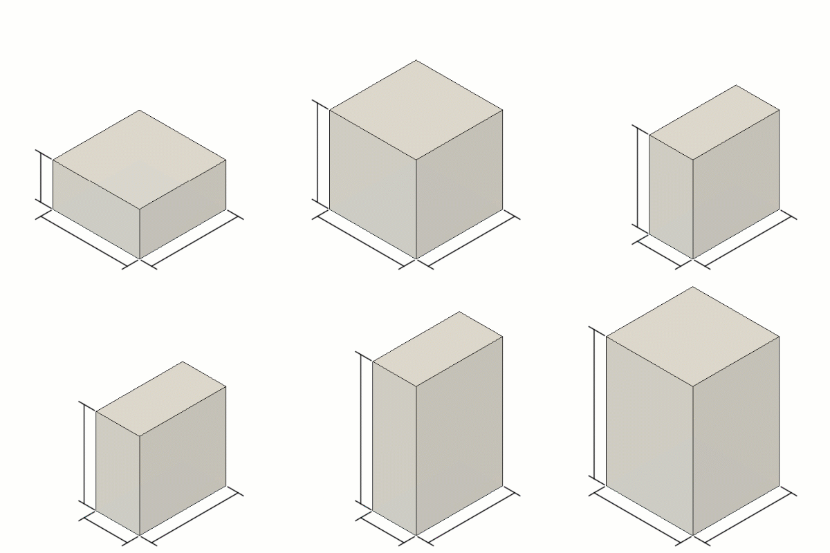
| Configuration | Length | Width | Height |
|---|---|---|---|
| 1 | 50mm | 50mm | 25mm |
| 2 | 50mm | 50mm | 50mm |
| 3 | 25mm | 50mm | 50mm |
| 4 | 25mm | 50mm | 75mm |
| 5 | 50mm | 50mm | 75mm |
Feature Parameters
You can configure Feature Parameters for most parametric features in the Timeline.
For example, you can configure aspects like Sketch Dimensions, Extrude Distance, Hole Diameter, Pattern Quantity, and Fillet Radius.
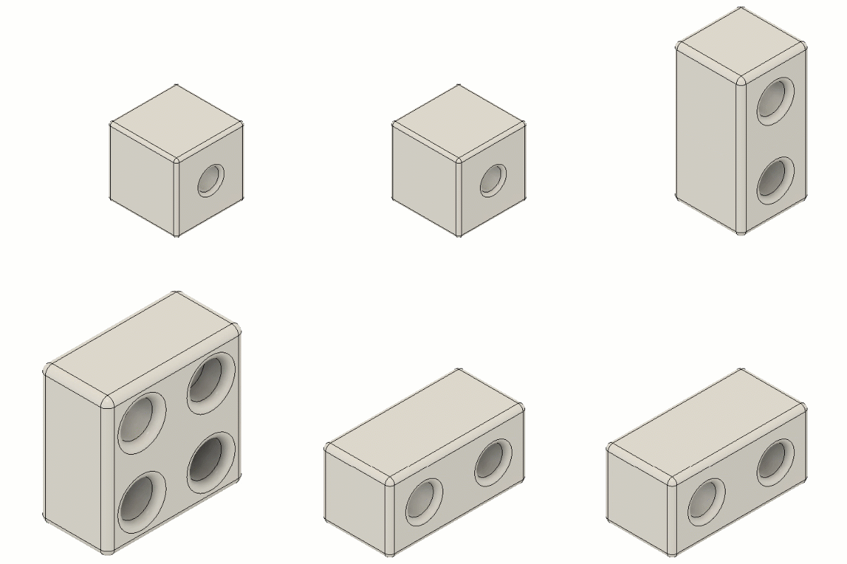
| Configuration | Sketch Dimension | Extrude Distance | Hole Diameter | Pattern Quantity Vertical |
Pattern Quantity Horizontal |
Fillet Radius |
|---|---|---|---|---|---|---|
| 1 | 50mm | 50mm | 15mm | 1 | 1 | 2.0mm |
| 2 | 100mm | 50mm | 20mm | 2 | 1 | 3.5mm |
| 3 | 100mm | 100mm | 25mm | 2 | 2 | 5.0mm |
| 4 | 50mm | 100mm | 20mm | 1 | 2 | 3.5mm |
Other Feature Aspects
In addition to parameters, you can configure additional aspects of certain features in the Timeline.
| Feature | Configurable Aspects |
|---|---|
| Joint | Component 1 Snap, Component 2 Snap, Flip |
| Thread | Modeled, Full Length, Thread Type, Size, Designation, Class, Direction |
| Hole | Modeled, Thread Offset Type, Thread Type, Size, Designation, Class, Direction, Standard, Fastener Type, Fit |
For example, you can configure both component Snaps and the Flip aspect of a single joint feature to control the position of one or more components relative to another.
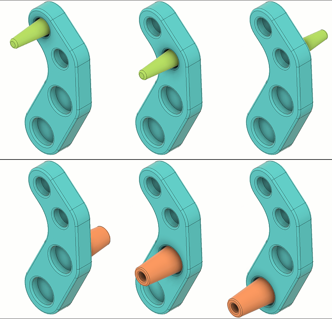
| Configuration | Snap 1 | Snap 2 | Flip | Suppress Component 1 | Suppress Component 2 |
|---|---|---|---|---|---|
| 1 | Component 1 | Hole 1 |  |
||
| 2 | Component 1 | Hole 2 |  |
||
| 3 | Component 1 | Hole 2 |  |
||
| 4 | Component 2 | Hole 3 |  |
||
| 5 | Component 2 | Hole 3 |  |
||
| 6 | Component 2 | Hole 4 |  |
Suppression
You can configure Suppression for most parametric features in the Timeline.
For ease of access, you can also configure Suppression of some objects from the Browser, like components and sketches. This suppresses the feature in the Timeline that created the object.
There are three suppression states:
 Unsuppressed
 Suppressed (explicit)
 Suppressed (implicit)
For example, you can configure suppression for components or modeling features to create different variations of a design.
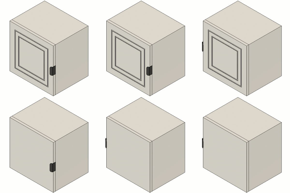
| Configuration | Component Left |
Component Right |
Extrude Cut Feature |
|---|---|---|---|
| 1 | |||
| 2 | |||
| 3 | |||
| 4 |
Configured Component Insert
To create a Configurable Assembly, you can configure the Insert feature of any Configured Component you've inserted into another design. This lets you select a different source configuration for each row in the destination design.
For example, you can insert a small configuration of a component into a design that represents a full assembly. Then you can configure the Insert feature of the configured component to use its small, medium, or large variant in each configuration of the overall assembly.
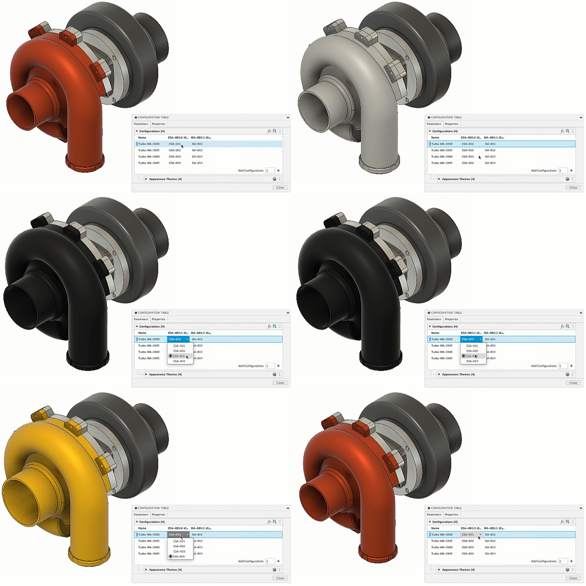
| Configured component to insert |
|---|
| CSA-001 - Small compressor scroll (clay) |
| CSA-002 - Medium compressor scroll (slate) |
| CSA-003 - Large compressor scroll (black) |
| CSA-004 - XL compressor scroll (gold) |
Standard Design Insert
You can configure the Insert feature of any Standard Design that is inserted as an External Component. This lets you select a different design to insert for each row of the destination design.
Visibility
You can configure Visibility for most objects in the Browser.
There are two visibility states:
 Visible
 Hidden
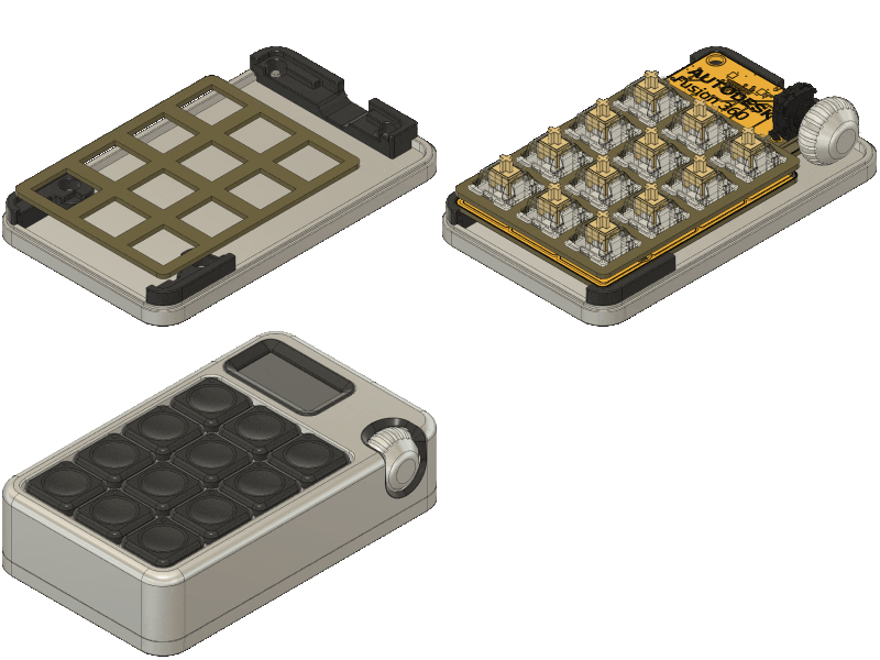
| Configuration | Manufacturing Step |
|---|---|
| 1 | Base assembly |
| 2 | Internal assembly |
| 3 | Enclosure assembly |
Physical Material
You can configure Physical Materials for the following objects in the Browser:
- Default Component
- Internal Components
- Bodies
For ease of access, you can also configure Physical Material for most components from their creation feature in the Timeline as well.
Once you configure an object's Physical Material, you can create, edit, and assign Themes to Configurations in the dedicated Physical Materials Theme Table.
For example, you can configure different physical materials to prototype or manufacture.
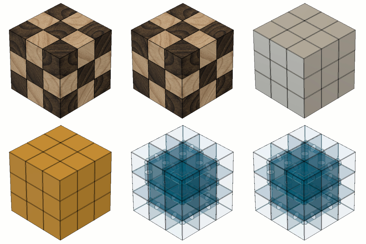
| Configuration | Physical Material |
|---|---|
| 1 | Wood |
| 2 | Aluminum |
| 3 | Opaque Plastic |
| 4 | Transparent Plastic |
Appearance
You can configure Appearances for the following objects in the Browser:
- Default Component
- Internal Components
- External Components
- Bodies within internal components
For ease of access, you can also configure Appearance for most components from their creation feature in the Timeline as well.
Once you configure an object's Appearance, you can create, edit, and assign Appearance Themes to Configurations in the dedicated Appearance Theme Table.
For example, you can configure different appearances for color or finish options in a product line.
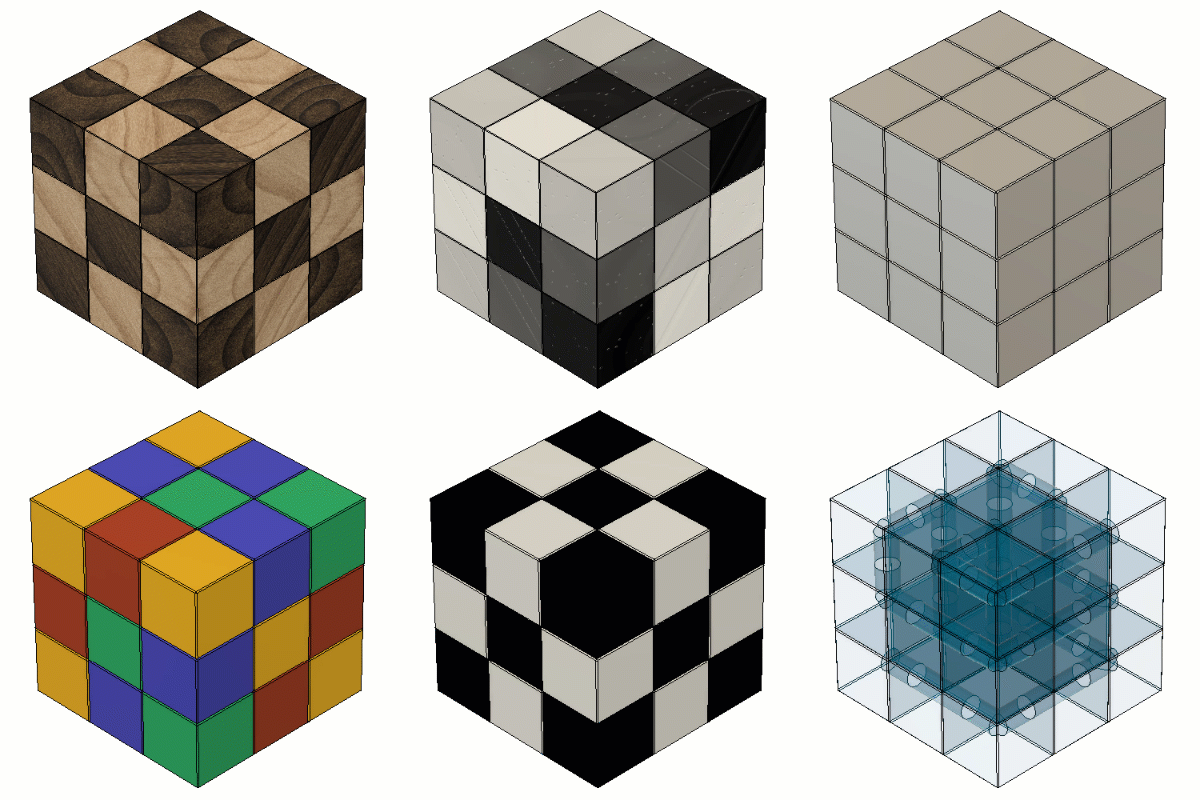
| Configuration | Appearance |
|---|---|
| 1 | Stained Wood |
| 2 | Painted Wood - Multicolor |
| 3 | Painted Wood - Monochrome |
| 4 | Painted Wood - Black & White |
| 5 | Polished Aluminum |
| 6 | Anodized Aluminum - Multicolor |
| 7 | Anodized Aluminum - Monochrome |
| 8 | Anodized Aluminum - Black & White |
| 9 | Plastic - Polymide |
| 10 | Plastic - Blue Acrylic |
Sheet Metal Rules
From the Browser, you can configure the Sheet Metal Rule for each sheet metal component in an assembly.
Once you configure a component's Sheet Metal Rule, you can create, edit, and assign Sheet Metal Rule Themes to Configurations in the dedicated Sheet Metal Rule Theme Table.
For example, you can configure different material and thickness options to determine which is best for a final folded product.
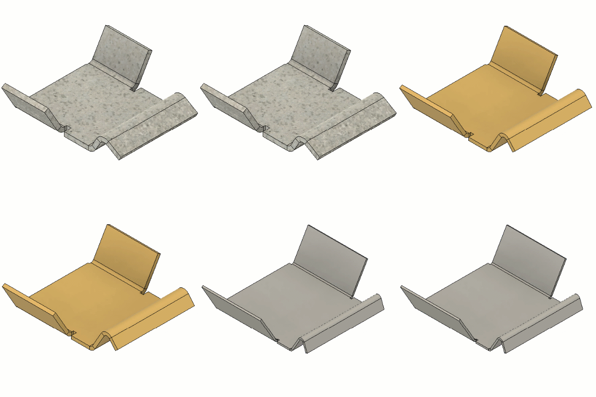
| Configuration | Sheet Metal Material | Sheet Metal Thickness |
|---|---|---|
| 1 | Steel | 2.75mm |
| 2 | Brass | 2.00mm |
| 3 | Aluminum | 1.00mm |
Plastic Rules
From the Browser, you can configure the Plastic Rule for each component with a plastic rule assigned to it in an assembly.
Once you configure a component's Plastic Rule, you can create, edit, and assign Plastic Rule Themes to Configurations in the dedicated Plastic Rule Theme Table.
For example, you can configure different plastic material options for an injection molding design, and use the Design Advice tool or the tools in the Simulation workspace to compare results to determine the best design.
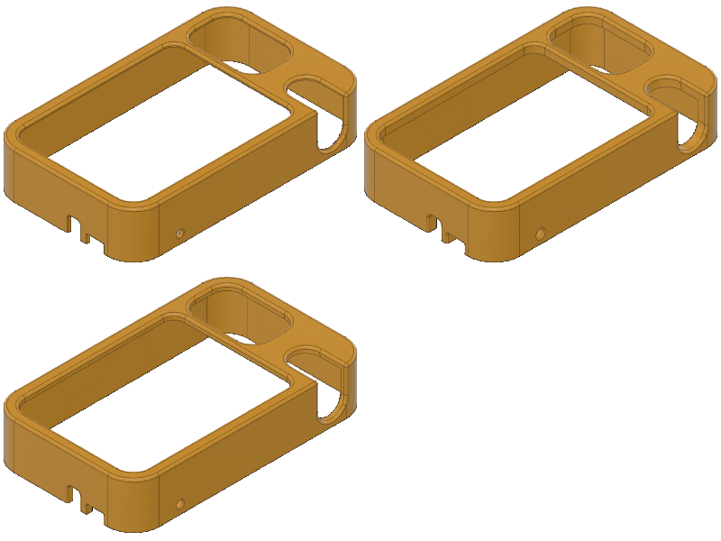
| Configuration | Plastic Rule | Plastic Rule Thickness |
|---|---|---|
| 1 | ABS | 1.00 mm |
| 2 | Nylon | 2.50 mm |
| 3 | Polypropylene | 3.00 mm |
Properties
From the Properties tab in the Configuration Table, you can configure the following Properties for each Configuration:
- Part Number
- Description
If you have a hub with collaborative editing, you can configure additional properties. Check for this icon ![]() next to the hub name to confirm. The following content only applies if you're working in a hub with collaborative editing.
next to the hub name to confirm. The following content only applies if you're working in a hub with collaborative editing.
Configuration part numbers
When you add a new configuration, Fusion creates and assigns a unique Part Number to the configuration. The default part number is based on the timestamp at the moment the configuration is created.
When you duplicate a configuration, Fusion assigns the same Part Number to the new configuration. The new configuration joins the group.
Configurations with the same part number now have shared part numbers and share all property values. If you update the properties for one configuration in the group, the properties are updated for all configurations with the same part number.
Internal component part numbers
When you create a new internal component, Fusion assigns the same part number to it across all configurations. Since they share part numbers, they also share all property values. If you edit the part number to a new value, it changes for the internal component across all configurations.
In configuration mode, you can configure the properties for internal components to add them to the table.