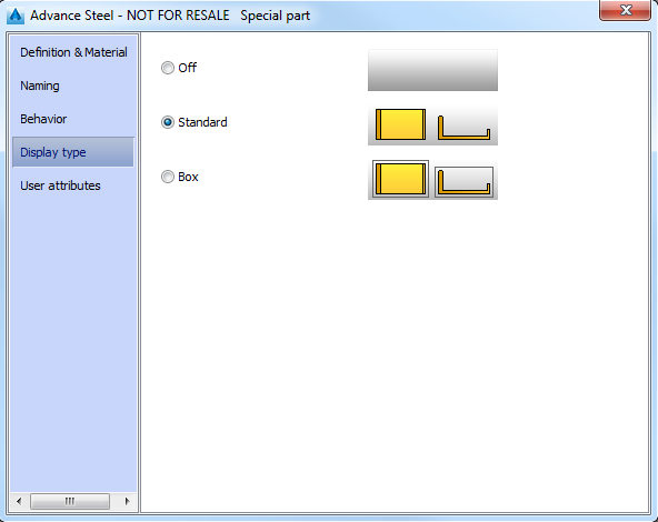
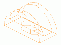
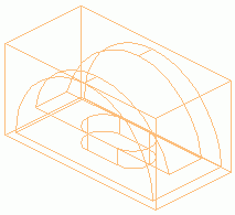
• Help Home
  • English (US)
    1. English (US)
    2. Čeština
    3. Deutsch
    4. Español
    5. Français
    6. Italiano
    7. Polski
    8. Português (Brasil)
    9. Русский
    • What's New
    • Introduction to Advance Steel
    • Get Started
    • 3D Modeling
      • 3D Modeling
        • Create and Modify Model Elements
          • Select Objects
          • Search Objects
          • Mark objects in the model
          • Work with Object Properties
          • Use Coordinate Systems
          • Snap on Location on Advance Objects
          • The Building Grid
          • Level Symbols
          • Workplanes
          • Create Model Elements
            • Beams
            • Grating
            • Plates
            • Processing
            • Bolts
            • Welds
            • Connections
            • Special Parts
              • Create a Special Part
              • Special Part Dialog: Definition & Material Tab
              • Special Part Dialog: Naming Tab
              • Special Part Dialog: Behavior Tab
              • Special Part Dialog: Display Type Tab
              • Special Part Dialog: User Attributes Tab
            • Concrete Elements
          • Create and Use Connections
          • Connections: Predefined Configurations
          • Quick Connections
          • Stairs and Railings
          • Place a Hand-Railing
          • Place a Monowills Hand-Railing
          • Place a Monowills Panelized Hand-Railing
          • Cladding for Walls and Roofs
          • Cladding Properties
          • Analytical Nodes
          • The Copy Tool
          • The Advanced Copy Tool
          • The Transform Elements Dialog
        • Display the Model
        • Check the Model for Errors
    • Numbering
    • Create and Manage Drawings
    • Collaboration
    • Dynamo for Advance Steel
    • Frequently Asked Questions
    • Developers
    • Advance Steel Installation
    • Autodesk Installation
    Share
    • Email
    • Facebook
    • Twitter
    • LinkedIn


    Special Part Dialog: Display Type Tab

    On this tab of the properties dialog box, you can choose how special parts are represented in the model.


    Display type Special part Description
    Standard Special part solid.
    Box Special part solid and bounding box.
    Parent topic: Special Parts

    Was this information helpful?

    Except where otherwise noted, this work is licensed under a Creative Commons Attribution-NonCommercial-ShareAlike 3.0 Unported License. Please see the Autodesk Creative Commons FAQ for more information.

    • Privacy Statement
    • Legal Notices & Trademarks
    • Report Noncompliance
    • © 2025 Autodesk Inc. All rights reserved