A dimension point selection rule contains settings for model objects and geometric restriction, point type, position on object or on main part.
- Model objects and geometric restriction - a filter for defining the objects used for selection of dimension points.
- Point type - the properties of the objects geometry used in the points selection process (e.g. objects contour, object features, holes, etc.).
- Position on object or on main part - the object points used for dimensioning (e.g., only the left or only the bottom of the object).
The Points selection rules can be shared by different dimension strategies. Consequently, modifications affect all the dimension strategies that use the modified points selection rule.
Select a predefined point selection rule from the list. The existing rules can be renamed and new rules can be added.
| Button | Function |
|---|---|
|
|
Define a new point selection rule. A copy of the current settings is created and a new item appears in the drop-down list. |
|
|
Rename a point selection rule. The current settings are saved under a different name. |
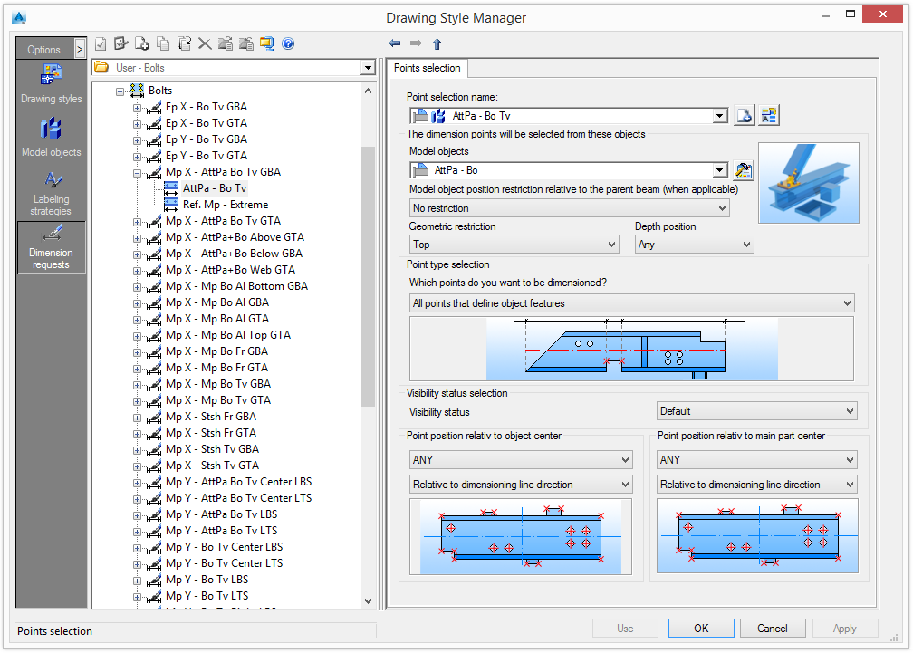
Select the model objects to be dimensioned
Select model objects and the geometric restrictions for defining the objects used in the selection of dimension points. ClickDefine the points to be dimensioned
Select the properties of the objects geometry used in the points selection process (e.g. objects contour, object features, holes etc) in the Point type selection area. Furthermore, points can be used as reference.
The following table lists the sub-styles for specifying which points from what objects will be dimensioned.
| Option |
| All as reference |
| All attaching parts as reference |
| All holes as reference |
| All points defining object processing as sub-objects |
| All points that are to be dimensioned of the object |
| All points that define object features |
| All points that define the object contour (without features) |
| Attaching parts at the objects |
| Bended beam inside as reference |
| Bended beam outside as reference |
| Bended beams inside |
| Bended beams outside |
| Center point as reference |
| Center point of the objects |
| Development lines |
| Extreme size of the objects in dimension direction |
| Holes in the objects |
| Main part Collision Dimensions |
| Main part Collision Dimensions as reference |
| Object contour as reference |
| Object features as reference |
| Object size as reference |
| Stencil point as sub objects (grouped together) |
| System as reference |
| System points of the objects |
| Template reference point as reference |
| Templates reference point |
It is possible to distinguish between three categories of point types:
- As reference -This option provides dimension points only when there are other dimension points; otherwise, those points will not be used. This point selection type is useful when no dimensions are necessary.
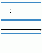
Example:
A dimension line if there is a hole, and if there is no hole in the main part, no dimension chain is created.
Points selection rule Result Holes - All features
Main Part - Extreme as reference
- Features and Contour
There is a difference between feature and contour dimension points.
In Advance Steel, there are two main types of feature processing:- Finite processing (e.g. rectangular contour feature)
- Infinite processing (e.g. shortening and cope features)
For dimensions, the object features points means the points created by the finite processing.
The object contour (without features) points means the points of the elements contour, including the points created by the infinite features.
- Beam end processing - Provides the dimension for the beam end contour points, including the points created by the finite processing that affect the beam end contour.
Examples:
Points selection rule Result Holes - All
Beam - Extreme as reference
Beam - Extreme
Holes - Beam
Holes - All
Beam - Extreme as reference
Center points as reference
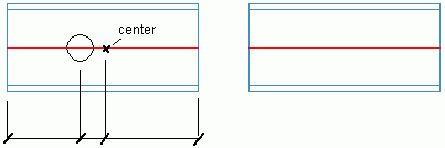
Holes - All
Beam - System as reference
Visibility status selection
Visible and hidden dimension points for each dimension definition and dimensioned elements are selected using the Visibility status.
| Option | Description |
|---|---|
| Default | The default option will be used. |
| Hidden |
Only the hidden objects will be dimensioned. 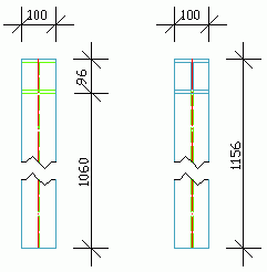
|
| Visible |
Only the visible objects will be dimensioned. 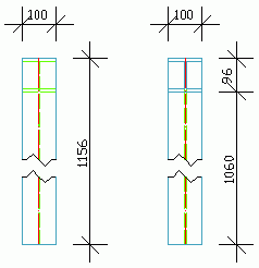
|
| Visible and hidden |
Visible and hidden objects will be dimensioned. 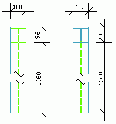
|
Point position on object
- Point position on object - used to filter the points depending on their position on the attached parts.
- Point position on main part - used to filter the points depending on their position on the main part.
The following restrictions are available:
| Option | Description |
|---|---|
| Any | All object points. |
| Bottommost | The most bottom point is used. |
| Bottom | The bottom points. |
| BottomLeft | The points on the bottom-left side. |
| BottomRight | The points on the bottom-right side. |
| Left | The points on the left side. |
| Left & Right Extremes | The points on the left side and the right extreme points. |
| Leftmost | |
| Right | The points on the right side. |
| Rightmost | |
| Top | The points on the top side. |
| Top & Bottom Extremes | The points on the top side and the bottom extremes. |
| TopLeft | The points on the top-left side. |
| Topmost | |
| TopRight | The points on the top-right side. |
The restriction refers to the dimension line direction or to the object direction. Only some of the object points can be dimensioned (e.g. only the left part or only the bottom of the objects).
| Option | Description |
|---|---|
| Relative to dimension line direction |
|
| Relative to object direction |
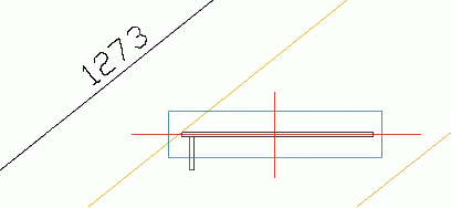
Example: The steps of a stair:
|
Examples: Point position on object and on main part.
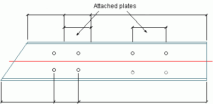
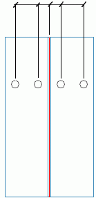
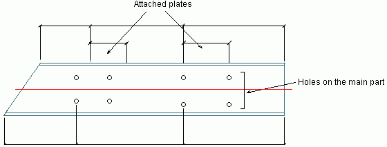
- The behavior of the Point position on object setting:
Use the Left restriction relative to the object for the attached plates and the holes.
Both attached plates and all groups of holes from the main part are dimensioned as shown in the following image:
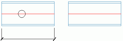
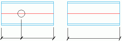
- The behavior of the Point position on main part setting:
Only the attached plate and the holes placed in the left side of the main part are dimensioned as shown in the following image: