Surface Tool Common Parameters
These sections describe important settings that are used by more than one surface tool.
Continuity (G0, G1, G2, G3)
The continuity setting specifies how one shape 'flows' into another at the boundary
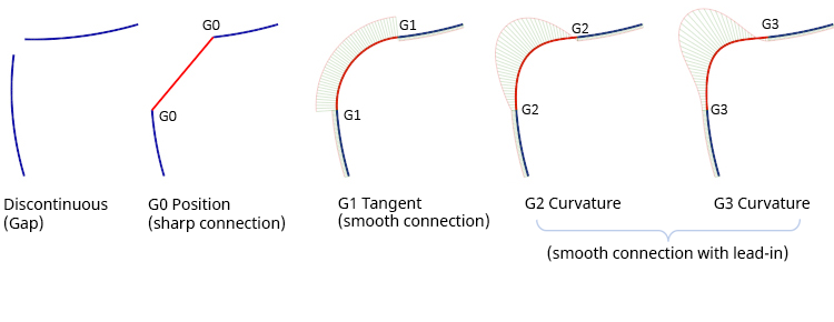
Positional (G0)
The endpoints of two curves meet, or the boundaries of two surfaces meet.
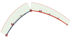
Tangent (G1)
Same as positional continuity, plus the end tangents match at the common endpoint. The two curves or surfaces appear to be traveling in the same direction at the join, but they may still have very different apparent “speeds” (rate of change of the direction, also called curvature).
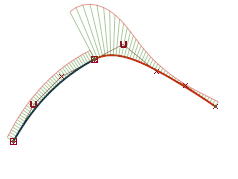
Curvature (G2)
Same as tangent continuity, plus the curvature matches at the common endpoint. The two curves or surfaces appear to have the same “speed” at the join.
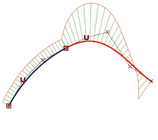
Curvature with constant rate of change (G3)
Same as curvature (G2) continuity, plus the rate of change in the curvature matches between the curves or surfaces.
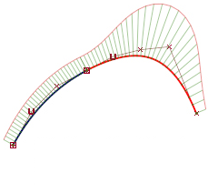
Implied Tangent and Tangent Angle (Square and Rail)
Implied Tangent – Try to keep tangency with an implied surface that shares this edge. The implied surface is the surface that would be created by mirroring the new surface.
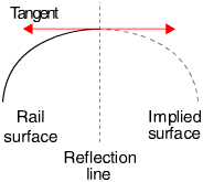
Implied Curvature – Try to keep curvature continuity with an implied surface that shares this edge. The implied surface is the surface that would be created by mirroring the new surface.
Implied Tangent and Implied Curvature are powerful features. They let you model one half of a symmetrical surface (such as a car body), and maintain continuity at the seam. When you duplicate the surface to create the other half, the seam will already be continuous.
Tangent Angle – Try to keep tangency at an angle with a surface that shares this edge.
The Rail Surface tool calculates the tangent angle at both ends of the common edge. If the two angles are different, Rail Surface blends between them to determine the angle to keep at every point along the edge.
A tangent angle of 0.0 (or 180, -180, 360) is equivalent to G1 Tangent continuity.
Calculating Continuity
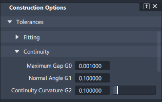
The accuracy with which continuity levels are achieved is determined by the Construction Options settings chosen by the user. Larger tolerance values will allow quicker calculation but less accurate results. Smaller tolerance values will provide more accurate continuity but may result in more complex surfaces and longer build times.
The Tolerance settings shown below are commonly used for production quality surfacing:
Continuity settings are available in the following surface tools:
- Rail
- Square
- Surface Fillet
- Symmetric Fillet
- Freeform Blend
- Profile Blend
- Profile Sweep
- Multi-Edge Blend
- Fillet Flange
- Tube Flange
- Panel Gap
- Round
- Ball Corner
- Corner Blend
- Surface Offset
Crown Options
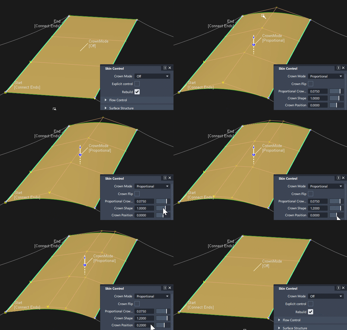
Where a surface tool would normally create a straight-line surface (for example Skin or MSDraft), the Crown option lets you add additional shape:
Crown Mode
Crown mode can be selected in the tool Control window, or using the in-canvas manipulator:
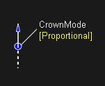
- Off - no options are displayed and a degree 1, 'ruled' surface is built.
- Proportional - The crown height is a percentage of the surface width. Creates either a degree 2 or degree 3 surface depending on the Crown Shape setting. Use this to maintain a similar character of surface shape across different widths.
- Absolute - The crown height is an absolute value. Creates either a degree 2 or degree 3 surface depending on the Crown Shape setting.
Crown Value
In the tool Control window, the slider range changes depending on the Crown Mode:
- Proportional - The Crown Value slider ranges from 0.0 to 0.1, but larger values can be entered into the field.
- Absolute - The Crown Value slider ranges from 1 to 10, but larger values can be entered into the tool window field.
To change the Crown Value using the in-canvas manipulator, drag the arrow. Use the left mouse button to adjust in 0.005 increments. Use the middle mouse button for fine adjustments.
Crown Flip
Click the dotted line opposite the arrow on the crown manipulator to flip the crown direction directly on the model.
Alternatively select the Flip Crown checkbox. (Typing a negative number into the Crown Value field has the same effect).
Crown Shape
The slider for Crown Shape behaves in a non-standard way.
A Crown Shape value of 1 is the default, and this keeps a single row of CVs in the centre (degree 2 surface).
Changing this value adds a second row of CVs (degree 3 surface). The position of the centre rows of CVs is determined by the value greater or lesser than 1:
- Crown Shape values less than 1 move these CVs closer to the edges of the surface.
- Crown Shape values greater than 1 move these CVs closer to the center.

Crown Position
The default Crown Position is set to zero and results in a symmetrical surface.
Adding a positive or negative value to the crown shape pushes the peak of the crown to the left or right.

Crown Type
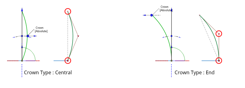
Only available in the MS Draft surface tool. The shape of the surface is the same with both settings, but the relationship to the draft angle changes:
- Central - The first and last CVs in the V direction follow the draft angle, and the surface crowns in the center of the draft surface.
- End - The second CV follows the draft angle. The height of the crown is the same, but the change in surface shape appears at the end.
Crown settings are available in the following surface tools:
- Skin (Two boundaries only)
- Multi-Surface Draft
- Surface Fillet (G0 Chamfer only)
- Freeform Blend (G0 on both sides)
Explicit Control Options
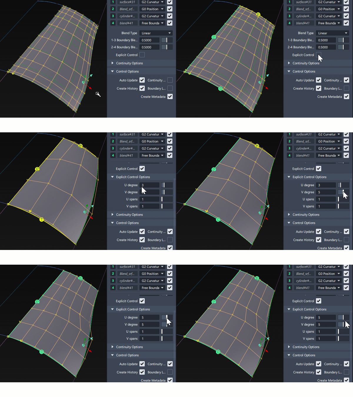
The Explicit Control option allows you to set the Degree and Spans of a curve or surface created or modified by the tool.
As this will affect the continuity achieved, it is recommended that you check the continuity results using the Control Options section in the tool, or the Evaluate > Continuity Check tool.
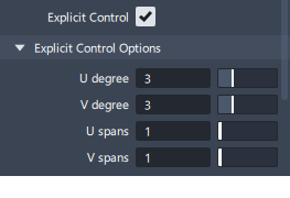
The Explicit Control Options section only appears when Explicit Control is selected in the tool:
Explicit Control Method 1 - Absolute U & V
If Explicit Control is selected, you can directly enter the values you want for Degree and Spans in the U (and V) directions. Pay attention to the continuity results as these are more likely to fail. Adjust the Degree and Spans values to achieve the required balance between continuity achieved and surface structure.
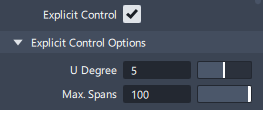
Explicit Control Method 2 - Max U Spans
Surface creation tools that specify continuity on two opposing edges typically use a maximum limit for the U Spans instead of an absolute setting:
- The Max U Spans setting in the tool will override the global setting Max Surf Spans in Construction Options. (Both default to a value of 100 in the first instance).
- This provides an upper limit, so the tool will only create as many spans that are needed to satisfy the tolerance criteria.
- When Bezier is selected in the Surface Structure section of the tool, the Max U Spans field is not displayed, as Bezier is, by definition, a single-span surface.
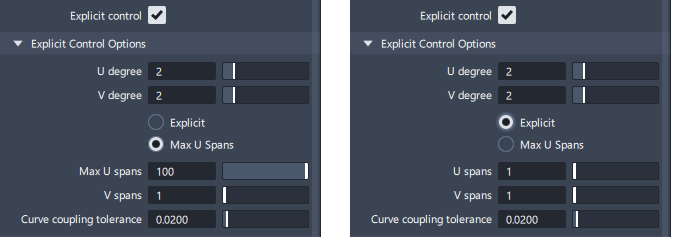
Explicit Control Method 3 - Choice of Absolute or Max values
Some tools combine the two options above and you can choose which to use:
When to Use Explicit Control Off
The default setting for Explicit Control is 'off'. This setting is most likely to result in closed surface models and requires less input from the user.
Tools refer to the Construction Tolerances to determine how accurately they must achieve Positional, Tangent or Curvature continuity. A fitting algorithm is then used that iteratively increases the degree and number of spans until those continuity values are achieved. In this way, the simplest surface that satisfies the tolerance settings is built.
(The maximum number of iterations is controlled by the Max Surf Spans setting, typically set to 100.)
When to Use Explicit Control On
You would typically use Explicit Control when you have a good understanding of the surface structure, and you want full control over the number of CVs you are working with. This becomes more important as your models move from concept designs towards production quality or Class A surfaces.
Explicit Control overrides the tool iterations to tolerance. It still tries to fit to the continuity values, but cannot always achieve it.
The key to using Explicit Control is to always evaluate the continuity achieved. You may need to adjust the degree or number of spans, or re-think your patch layout with smaller surface segments to get a good result.
The Explicit Control Options are in the following surface tools:
- Skin
- Rail
- Square
- Surface Fillet
- Symmetric Fillet
- Freeform Blend
- Profile Blend
- Fillet Flange
- Tube Flange
- MS Draft
- Ball Corner
- Corner Blend
- Surface Offset
Flow Control and Modify Range
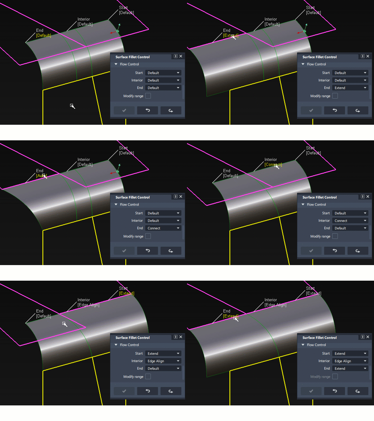
Flow Control determines the behaviour of the boundaries of surfaces in relation to the input surface boundaries. The four main options are shown below:

- Edge align – The tool tries to colinearly align the surface edges or isoparms (for single surface) to the edges of the boundary surfaces in the V direction.
- Connect – The edges of the blend surfaces meet the start and/or end points of the boundaries.
- Default – The edges of the surface meet the boundaries at a 90 degree angle, matching the length of the shorter input surface boundary.
- Extend – The surface is extended so that it reaches to the end of the longer input surface boundary.
The settings can be changed either by clicking on the in-canvas controls to cycle through the possible options, or by directly selecting an option in the Flow Control section:
Modify Range
This can be a section on its own, or an option within the Flow Control tab.
When this option is selected there are two ways to control the range:
- Sliders appear in the control window with Start and End values of 0.0 and 1.0 respectively which define the original extent.
- Blue arrow manipulators appear in-canvas on the selected fillets. Drag these arrows to modify the extent of the fillets across the input surfaces.
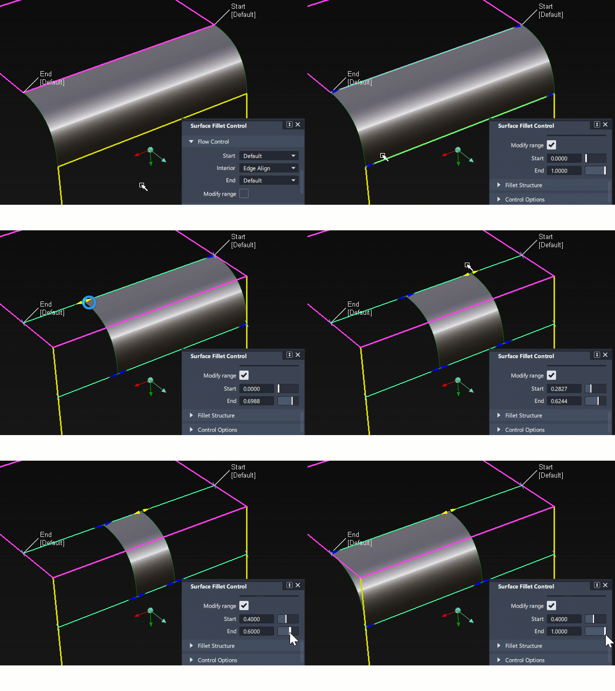
- Surface Fillet : The Start or End of the range can only be modified if the flow control option for that end was set to Default.
- Freeform Blend: These are not available if the Flow Control is set to Edge align for either the Start or End.
Flow Control and/or Modify Range Options are in the following surface tools:
- Skin
- Profile Sweep
- Surface Fillet
- Symmetric Fillet
- Freeform Blend
- Fillet Flange
- Tube Flange
- Panel Gap
- MS Draft
- Stitch Seam
Surface Structure
The Surface Structure section appears for tools that potentially create multiple surfaces in a group. It gives you control over the spans and segments created within the surface group.
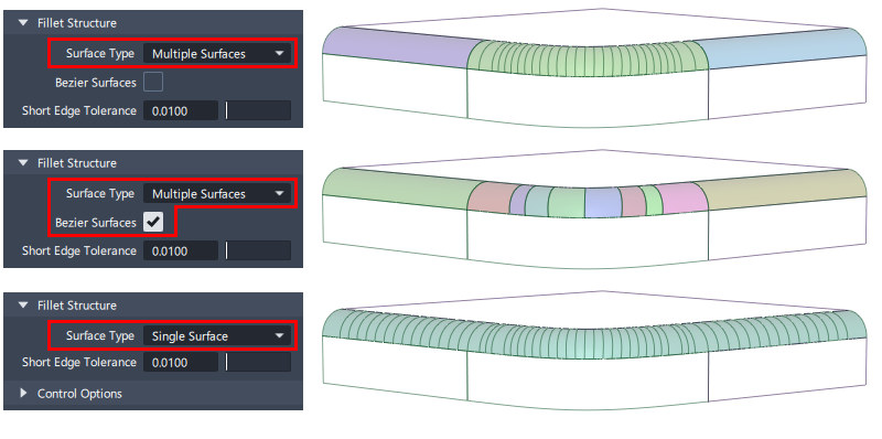
Surface Type
Multiple Surfaces - (Default) Multiple surfaces, corresponding to the boundaries between the original surfaces, are created, and the surfaces are grouped.
Multiple Surfaces with Bezier On - This option builds each surface as a Bézier patch (single-span NURBS). Choosing Bezier will typically result in more surfaces, smaller in size (depending on the complexity of the input surfaces).
Single Surfaces - A single skin surface is built that crosses multiple input boundaries.
Short Edge Tolerance (should be Min. Edge Length)
This is typically left unchanged at the default value of 0.01mm, as this setting is used to minimise the creation of tiny surfaces. If the tool calculation results in any surface that is smaller than the setting, then that small surface is replaced by an extension to an adjacent surface:
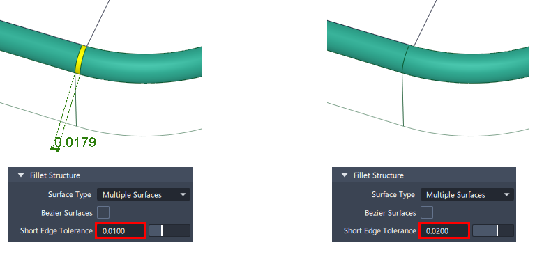
Surface Structure Controls are in the following surface tools:
- Surface Fillet, Symmetric Fillet
- Freeform Blend, Profile Blend
- Skin
- MS Draft
- Profile
- Panel Gap, Fillet Flange, Tube Flange
Form Factor and Fillet Specify
A fillet (or blend) needs to be specified differently when it is G1 Tangent or G2/G3 Curvature as the fillet will no longer have a constant radius:
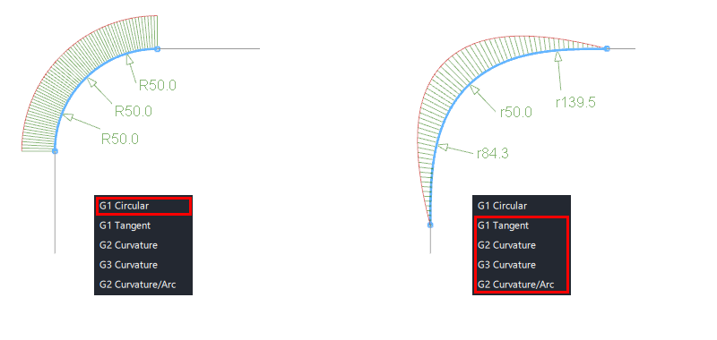
There are three values that affect the size and shape of a non-circular fillet:
- Center radius
- Tangent offset
- Form factor
These values are inter-dependent - only two need to be defined to specify the fillet - the third value will be calculated by the tool.
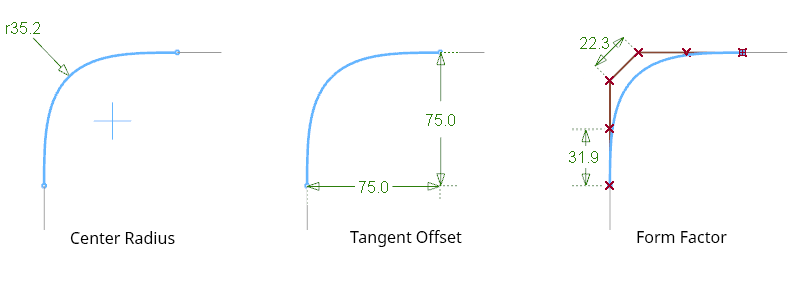
Specify
The Specify option may appear when G1 Tangent or G2/G3 Curvature continuity have been selected. This selects which two of the three values you wish to enter:
- Center radius : Centre radius and Form Factor can be input.
- Tangent offset : Tangent offset and Form Factor can be input.
- Both : Centre radius and Tangenet Offset can be input.

In some tools the Specify option in not used and a Radius value is the only option available:
- Corner Blend - Base Radius
- Round - Initial Radius
Form Factor
The Form factor controls the shape of a fillet or blend when G1 Tangent or G2/G3 Curvature are selected.
It is used as the ratio between the lengths of the boundary hull and the central hull(s). Hulls between the boundary and central hulls are interpolated linearly.
The value is between 0.1 and 2, with a value of 1 being equal spacing.
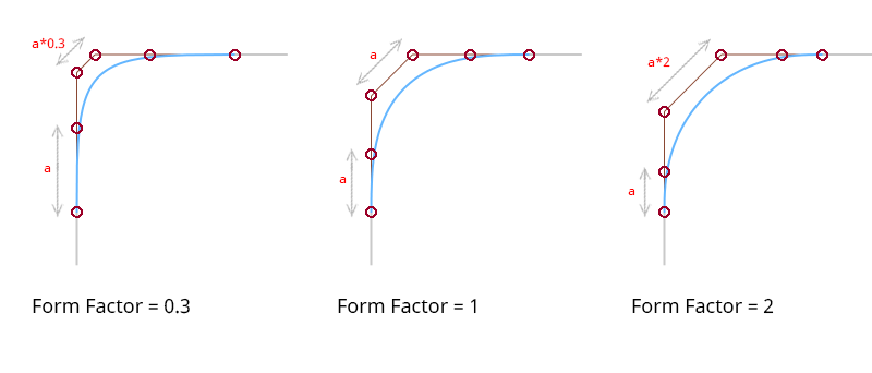
Fillet Specify and/or Form Factor is used in the following surface tools:
- Surface Fillet
- Symmetric Fillet
- Freeform Blend
- Fillet Flange
- Tube Flange
- Panel Gap
- Round
- Corner Blend
Axis and Vector Options
The Axis or Vector Options are used to specify either:
- A vector direction
- A plane that is orthogonal to the vector

Specify Vector Direction
- X, Y, Z - Specifies a vector direction along that axis. This can also be selected in-canvas when the manipulator is displayed.
- View - Specifies a vector normal to the current view. The vector is not drawn in the view windows. If the current view is changed, click Refresh View Vector to update the vector. Results will be more predictable if the view is orthogonal rather than perspective.
- Picked - Lets you pick an existing vector in the view, or specify the name of an existing vector in the Picked Vector field.
- Normal - The projection is done along the surface normals instead of using a single vector direction.
- Manip - This option is selected automatically when you manually modify a manipulator in the view.
Managing Vectors
- Refresh Vector - This button only appears if View is selected. Click it to update the vector if the view has been modified.
- Retain Vector - Converts the selected X,Y,Z or View direction to an independent vector in the scene. The tool window changes to 'Picked', and the projection direction is now controlled by the vector created.
- Create Vector - This option allows you to create a vector by selecting two points, or select an existing vector, followed by the 'Accept' button. This is then used as the axis for the revolve.
Set the vector direction with the manipulator
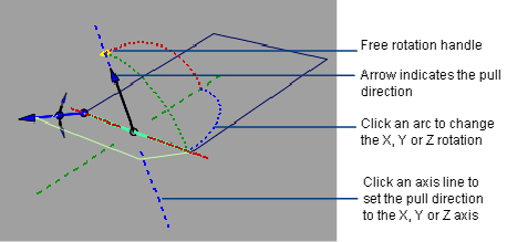
- Click an axis line to set the pull direction.
- Click the pull direction arrow to reverse its direction.
- Click one of the arcs, then drag the mouse left and right to change the pull direction.
- Click the free rotation handle to rotate freely in all directions.
- Click an existing reference vector to align the manipulator with it.
Axis and Vector Options are used in the following surface tools:
- Revolve
- Fillet Flange, Tube Flange, Panel Gap
- MS Draft
The following rules apply:
- The surface direction always respects the current coordinate system.
- If a surface was created in one set of coordinates (construction plane), and is later query-edited in a different one, the Refresh Vector button can be clicked to update the direction.
Control Options
Control Options are used in all surface tools with Control Windows (excluding Combine Surfaces).
Auto Update
Automatically updates the surface as you change settings in the Control Window. If your surface is very complex and takes a long time to update, turn this option off and click the Update button when you want to update the surface.
Create History
This option is on by default in all tools, and it creates two Construction History links:
History between the inputs (for example boundary curves) and the surface created.
History between the surface created and the settings in the tool Control Window. These can be modified by re-invoking the tool window, either by using the Query Edit tool, or by selecting the resultant geometry and single clicking on the tool icon that was used to create it.
Create Metadata
Metadata stores the tool window settings used when each item of geometry is created. This can be used to populate the settings in a tool window for the next build by:
- First select the source geometry - the source object must have it's construction history deleted. (Make a temporary copy if you want to keep the history).
- Select the tool (it must be the same tool as was used for the source geometry).
- You are prompted to load the metadata settings into the tool window, ready for the next build.
To display metadata :
- In the Information Window, if an object has metadata it displays in the Metadata tab.
- In the Query Edit tool, right-click on an object created with construction history.
Continuity Check
If this box is checked, continuity locators appear along the boundaries between input surfaces and the created surfaces indicating the level of continuity achieved.
(Ref - interpret continuity check)
Inter Continuity Check
Displays continuity locators between the surfaces created. This is particularly useful when you use the Bezier option to create single-span surfaces, as you will typically be working at the production quality level and so you'll want to watch out for and fix any small continuity errors.
Chain Select
If this box is checked, selecting a boundary input curve also selects all other boundary curves that are tangent continuous with it.
Trim Type or Auto Trim
- Automatic – Automatically trims the original surfaces back to the contact line.
- Curves-on-surface – Creates curves on surface along the contact lines, allowing you to trim manually.
- Off – Does not trim the original surfaces.
