Path-Based Pressure Networks
Dynamic path-based pressure networks make it easier to create and modify pressure networks in your Civil 3D drawings.
In this Have You Tried article, we’ll look at using the path-based pressure networks tools to create and modify the layout of pressure network pipe runs in plan and profile views.
In each Have You Tried article, we profile a useful feature or workflow in Civil 3D. We look across what's new, what's been around for a while, and we identify features that can improve your experience with Civil 3D while making you and your team more productive.
Do you have a feature you want to see covered? Provide your feedback at the bottom of the page and let us know in the comments section.
What is it?
Use the pressure network features to generate 3D models of pressure networks, such as water distribution networks. The pressure network features use catalogs of pipes and parts for realistic modeling and easy labeling.
Dynamic path-based pressure networks were introduced in Civil 3D 2021 and make it easier to create and modify pressure networks in your Civil 3D drawings.
Why use it?
The path-based pressure network tools make it easier to modify the layout of pressure pipe runs horizontally and vertically.
- Modifying the pipe run path will update the locations, lengths, and angles of the connected pressure network parts.
- You can add or remove bends and PIs along a pipe run and add branch fittings at the intersections of pipe runs.
- The vertical layout can be dynamically linked to a surface profile and manually overridden in user-defined station ranges.
Where do you find the tool?
On the Home ribbon tab, on the Create Design panel, click Pipe Network ![]() Pressure Network Creation tools or Pipe Network
Pressure Network Creation tools or Pipe Network ![]() Create Pressure Network From Object.
Create Pressure Network From Object.

Note: These new tools replace the older part-based pressure network tools, which are still accessible in Civil 3D from the Prospector tree.
How do I use it?
Creating a pressure network in plan view involves specifying default settings in the Create Pressure Pipe Network dialog box, and then using the tools on the Pressure Network Plan Layout ribbon to lay out the pressure network by sketching a pipe run. Layout can be done in disconnected pipe runs, which you connect later by inserting parts, or as continuous segments.
You can also create a pressure network from an existing object in the drawing, such as an alignment, which is covered in this article.
For pressure networks, the initial vertical design information is created along with the horizontal design. When you create the pressure network in plan view, you can specify a Reference Surface and Cover value in order to place the water main at the minimum required depth below (or distance above) the surface. These settings are what allow a 3D model to be created from the very beginning of the design process.
You can then refine the vertical layout in profile view as needed to achieve a best path.
Use case
One use case for path-based pressure networks is for laying out a residential subdivision that requires a water distribution network to be designed.
Start by creating a pressure network that is offset from an existing alignment.
Open a drawing that has an existing alignment you want to create a pressure network along.
Click Home tab
 Create Design panel
  Pipe Network
  Create Pressure Network from Object.
Select the alignment in the drawing:
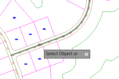
In the Create Pressure Network From Object dialog box, specify the following settings:
Network name: Specify a name for the pressure network.
Parts list: Click the Edit Current Selection option and check the parts list to ensure it has the diameter of pipe and corresponding elbows you need.

Review the parts list, add parts that you need, and click OK.
In the Create Pressure Network From Object dialog box, select the pipe size to use from the Pipe Size list.
Specify the surface information. Select a surface from the Reference Surface list and select the Create Surface Profile to Follow check box:

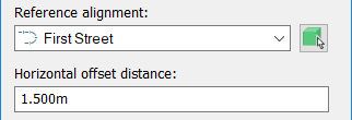
Select a reference alignment from the Reference Alignment list that will be used for station and offset values.
Then specify a Horizontal Offset Distance to offset the new pipe run relative to the selected object (enter a negative value to offset a distance to the left of the object, or a positive value to offset to the right):
Specify a Cover value:

Click OK to create the pressure network.
The pressure network is created at an offset from the alignment.
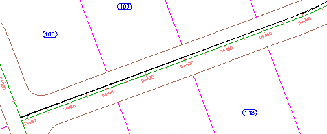
Select the new pipe run in the drawing to display the Pressure Network Contextual ribbon.
On the Pressure Network contextual ribbon, on the Profile panel, click Pipe Run Profile to display the Pipe Run Profile Settings dialog box.
Under Offset Style, select Cut Length.
Under Draw Profile In, select New Profile View.
Click OK to display the Create Profile View wizard.
Click the Next button until you reach the Pipe/Pressure Network page.
Review the pipe and fitting list to ensure all the desired pipes and fittings are included.
Click Create Profile View.
Select a location in the drawing and click to place the profile.
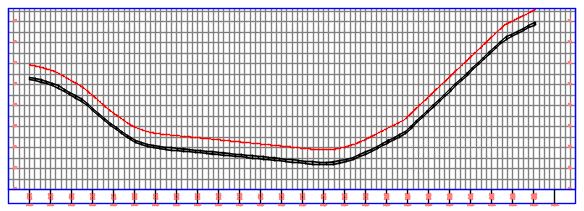
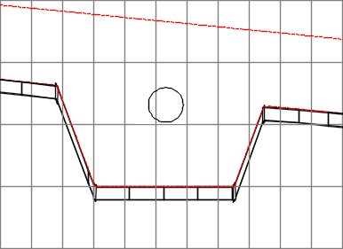
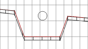
Next, you can add an override to the pipe run profile so that you can design around a crossing obstacle such as a gravity network pipe, shown below as a circle.
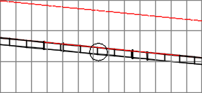
Select the pipe run in the profile view.
On the contextual ribbon tab, click Pipe Run Profile.
In the Pipe Run Profile Settings dialog box, click the Overrides tab.
Click the Add Offset Preferences for a Station Range button to add an override.
Define the start and end station for the override range by picking stations in the drawing.
Clear the Dynamic check box.
Select the Clean Up PVIs check box.
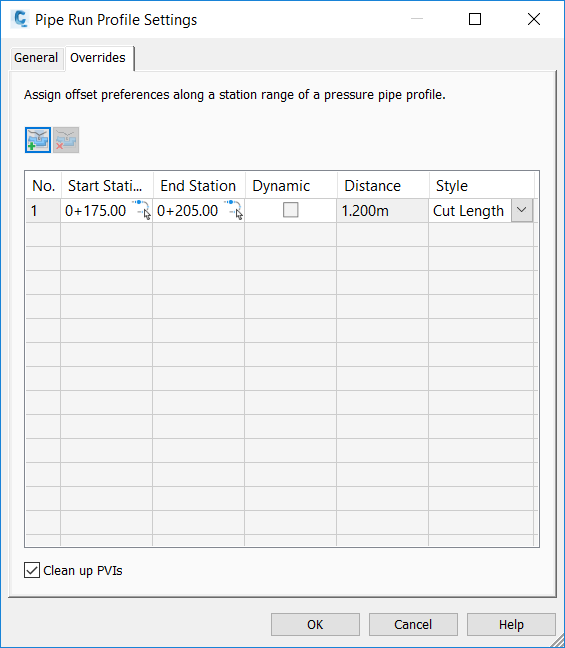
Click OK to create the range in the drawing.
Select the pipe run in the profile view and click Add Bend/PVI from the Layout panel.
Click to add bends to the pipe run so that the pipe run is moved around the obstacle.
Press ESC to deselect the pipe run.
Now the majority of the pipe run is following the surface profile, except for the region in which the override was created.
