
Use the options on the Solids > Set View menu to control the view displayed in the Solids window.
The following options are available:
Default — Set the default view.
Best Fit — Set the view so the model fits in the Solids window.
XY View — Set the XY view.
YZ View — Set the YZ view.
ZX View — Set the ZX view.
Isometric View — Set the Isometric view.
View Normal to Face Plane — Sets the view normal to the current face plane.
View Normal to Selected Surface — Sets the view normal to the currently selected planar surface.
Shaded Wireframe View — Displays the solid model in shaded mode with wireframe edges.
Shaded View — Displays the solid model.
Wireframe View — Displays the model using a wireframe representation.
Wireframe Silhouette — Displays the model using a wireframe representation including the model's silhouette edges.
Hidden Line View — Displays the model using a wireframe silhouette view, but with no hidden edges visible.
Drafting Hidden View — Displays the model using a wireframe silhouette view with hidden edges displayed in a different color.
Show Part Origin — Shows or hides the origin of the solid model.
Show Part Axes — Shows or hides the part axes in the Solids window.
Show Toolpath Points — Shows or hides the points in a toolpath that has been verified.
Use this menu option to display toolpath points for a toolpath on a solid model.
When the option is selected, PartMaker displays the points in a toolpath on the solid model. For example:
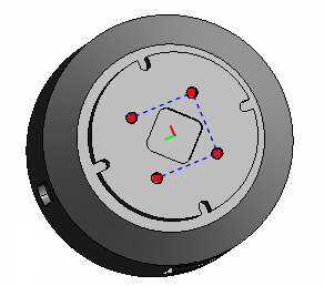
This option is also available on the Solids Windows toolbar.
Show Tool Axes — Shows or hides the tool axes for a toolpath that has been verified.
Use this menu option to display the tool axes for 4- or 5-axis simultaneous toolpaths or toolpaths imported from a PowerMill project.
When this menu option is selected, PartMaker displays the tool axes on the solid model. For example:
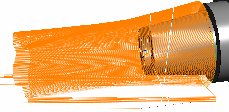
This option is also available on the Solids Windows toolbar.
Show Surface Group Colors on Solid Model — When selected, this option displays the surfaces belonging to a particular surface group using that group's color.
Background Color — Use the options in this submenu to change the background color of the window:
- Top Gradient Color — Select this option to change the graduated color displayed at the top of the window.
- Bottom Gradient Color — Select this option to change the graduated color displayed at the bottom of the window.
- Datum Color — Use the options in this submenu to specify the color of each coordinate axis (X, Y, and Z).
Show Part — Select this option to show or hide the part models for all stocks. This option is available only when you are using the Solids window in Setup Assembly Mode.
Show Stock — Select this option to show or hide the stock when you are using the Solids window in Part Mode.
Part Mode — Displays the part model in the Solids window. This option is applicable only in PartMaker/Mill when using both part models and setup assembly models in the Solids window.
Setup Assembly Mode — Displays the setup assembly in the Solids window. This option is applicable only in PartMaker/Mill when using both part models and setup assembly models in the Solids window.