
PartMaker uses pattern curves for:
- The 3D Offset finishing strategy (when Finishing is selected on this dialog).
- The Pattern finishing strategy (when Projection is selected on this dialog).
For projection machining, PartMaker projects profile curves onto the solid model or user-defined surface to create a toolpath.
When you select Pattern Curve as the curve type, the following settings are available on the Curve Properties dialog:
Used in Operation — Select the operations in which the profile curve is used:
- Roughing — This option is not available for pattern curves.
- Finishing — Select if the curve is used in the finishing operation.
- Remachining — This option is not available for pattern curves.
- Projection — Select if the curve is used in the projection operations.
Style — PartMaker displays the style of the curve:
- 2D curve — 2D curves are defined in the 2D CAM Face window.
- 3D curve — 3D curves are defined on the solid model in the Solids window. PartMaker displays 3D curves over the solid model, as they were programmed. 3D curves are not permitted in a Mill Cylinder Face window.
Distance From Face Origin — Enter the distance from the Face Origin at which PartMaker displays the 2D curve. The distance is measured in the direction that is perpendicular to the Face plane. This value must be the same for all curves in a Surface group. Therefore, if you change this value, PartMaker automatically updates all other curves in the group to use the same value.
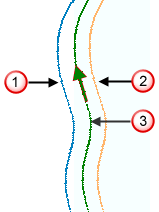
Tool Position — Select an option to specify the position of the tool (Left, On, or Right) relative to the toolpath's profile.
- Left — Select for the tool axis stays to the left of the curve by a distance equal to the tool radius (see
 ).
). - Right — Select for the tool axis to stay to the right of the curve by a distance equal to the tool radius (see
 ).
). - On — Select for the tool axis to pass through the curve (see
 ).
).
The Left and Right options apply only to projection pattern curves for a Pattern finishing strategy.
All the pattern curves used in a Pattern finishing toolpath must have the same tool position.
When using a 4- or 5-axis simultaneous toolpath, the Tool Position is automatically set to On and cannot be changed.
Boundary Type — This is not available when defining pattern curves.