A Face window is where you define geometry (when in CAD mode) or groups of part features, such as holes and profiles (when in CAM mode) that need to be machined.
You can view the Face windows and any groups of part features programmed in those Face windows in the Job Explorer pane.
Use the CAD/CAM Switch in the bottom left of the Face window to switch between CAD and CAM modes:
 indicates you are in CAD mode and
 indicates that you are in CAM mode.
Icons
Using the icons on the left side of a Face window you can specify new hole locations and create new profiles. One icon is always selected to indicate the current mode.
Turning icons
The following icons are available when programming turning operations in a Face window in CAM mode:

 Zero icon — Use this icon to define a new part origin using
snap modes.
Zero icon — Use this icon to define a new part origin using
snap modes.
 Define Profile icon — Use this icon to create a profile using
snap modes. This icon is available only if a profile group already exists and is selected. This icon is displayed in the following
PartMaker faces:
Define Profile icon — Use this icon to create a profile using
snap modes. This icon is available only if a profile group already exists and is selected. This icon is displayed in the following
PartMaker faces:
- Turn
- Mill ZX Plane
 Chain Geometry icon — Use this icon to define a profile, by selecting an end point of a line or an arc.
PartMaker automatically finds all connected lines and arcs. This icon is displayed in the following
PartMaker faces:
Chain Geometry icon — Use this icon to define a profile, by selecting an end point of a line or an arc.
PartMaker automatically finds all connected lines and arcs. This icon is displayed in the following
PartMaker faces:
- Mill ZX Plane
- Turn
 2-Point Chain icon — Use this icon to define a profile by selecting its start and end points on a contiguous piece of geometry.
This icon appears in the following PartMaker face windows:
- Turn
- Mill XY Plane
- Mill 5 Axis Plane
- Mill ZY Plane
- Mill ZX Plane
- Mill Polygon
- Mill End, Polar
- Mill Diam, Polar
- Mill Cylinder
- WireEDM
 Profile Info icon — Use this icon to select an element(line or arc) on the profile curve and view information about the element on the
Profile Info dialog. This icon is available only if a profile group already exists.
Profile Info icon — Use this icon to select an element(line or arc) on the profile curve and view information about the element on the
Profile Info dialog. This icon is available only if a profile group already exists.
CAD/CAM switch — Use this button to switch between CAD and CAM modes in
PartMaker. When the
icon is displayed, it indicates that
PartMaker is in CAM mode. Clicking the button switches
PartMaker into CAD mode.
Solid model icons for programming on solids
Layout icons
 Split Screen icon — Click this icon to split the display, so that the Face window and the Solids window take up an equal amount of space. This icon is displayed only when a solid model is loaded.
 Maximize Solids Window icon — Click this icon to maximize the Solids window. This icon is displayed only when a solid model is loaded.
 Minimize Solids Window icon — Click this icon to minimize the Solids window. This icon is displayed only when a solid model is loaded.
Color Palette
In CAM mode, use the Color Palette change the color of a group:
- Select a group in the Job Explorer pane.
- Click a color in the Color Palette to make it the sample color:
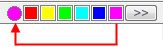
To display more colors, click >> to display the Color dialog.
- Click the sample color. PartMaker changes the color of the group to the sample color.
Displaying the axes
You can display the axes in a face window by selecting View > Show Axes.
Displaying the grid
You can display the grid in a face window by choosing View > Show Grid.
Displaying the boundaries
You can display the boundaries in a face window by choosing View > Show Boundaries.
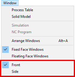
Displaying different Face windows
When you have multiple CAM Face windows, you can quickly switch between them by selecting the name of the Face window you want to display from the Window menu. For example: