
Preferences Tab
Surfaces Settings
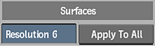
Default Resolution field
Displays the default geometry resolution (number of polygons) of surfaces. You can also change the geometry resolution of specific surfaces in the Surface menu.
The lower the value, the better the resolution and the greater the processing time required to interact with the image. A value of 1 creates one polygon per pixel on a surface, affording accurate displacement and lighting.
Use this field when Exploding Objects and Surfaces with a particle generator and when using hardware texture mapping.
Apply To All
Click to apply the geometry resolution in the Resolution field to all surfaces. Since you can change the resolution of specific surfaces in the Surface menu, you can use this button to re-apply the default resolution to all surfaces.
Filtering Settings
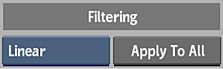
Default Filter option
Select the type of filtering to be set as the default when creating surfaces and maps.
Apply To All
Click to apply the default filter to all existing surfaces and maps.
Blending Settings
Default Premultiplication option
Select the default blend operation premultiplication setting.
Apply To All
Click to apply the default blend premultiplication setting to all existing surfaces and geometries.
Lightbox Settings
Lightbox Shading
Sets the default behaviour of Lightbox nodes when the attached Light is not active.
Apply To All
Click to apply the default Lightbox Shading setting to all existing lights.
Miscellaneous Settings
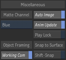
Matte Channel option
Select which channel is displayed as transparent by default. This can be useful for a multichannel clip to display only the Red channel matte, for example.
Auto Image
Enable to add an image node and axis automatically in the schematic when new media is added.
Animation Update
Enable to update properties such as position, rotation, and colour in the scene. When disabled, animated objects do not move, but keep the position of their current value. Disable to copy keyframe values from one frame to another.
Play Lock
Enable to update the animation settings according to the frame or timebar position as you move through the clip while keeping it locked at the current frame.
When Play Lock is disabled and you use > or < to play the resulting clip, each frame is loaded and displayed in sequence in the image window.
Perspective Camera
Enable to automatically switch to the Perspective Camera when framing the contents of the viewport using the Frame All or Frame Selection keyboard shortcuts. Disable to frame using the active camera.
Shift-Snap
Enable to use the Shift key to snap-to-ZDepth: Shift+drag an axis in the Viewport and it snaps to available ZDepth information. Disable to Shift+drag an axis and have it snap-to-Locators in the Analyzer.
Display Settings
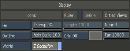
Icons option
Sets object icon (axes, borders, control points) and wireframe display options. Selected displays icons only for the object currently selected in the scene. Group Off displays every icons except for objects nested in Group nodes. Use option the Cycle Icons Draw Modes keyboard shortcut to cycle through the options.
Icon Transparency field
Displays the transparency level for icons and wireframes in the scene.
Selection Highlight option
Select the type of highlight used to identify the objects that are selected in the viewport.
Axis Scale field
Displays the size of axis icons in the scene.
GMask Vertices
Enable to always display GMask vertices. Disable to hide the vertices of GMasks that are not selected.
Z-depth Occlusion
Enable to have Z-depth occlusion affect Action widgets such as axis, light, and cameras. It creates a true 3D experience in terms of viewing, but hides occluded widgets.
Space Selection
Select the space for transforms performed using a 3D Manipulator. In Object space, the manipulator sticks to the object's axis orientation, ideal for translations. In World space, the manipulator follows the World's frame of reference, ideal for rotations. In Camera space, the manipulator stays in the camera's XY plane.
Ruler
Enable to display the ruler in the scene area. Use the arrows at each extremity of the ruler to place the beginning and end of the ruler anywhere in your scene view.
Ruler Define
Enable to define real unit measurements, such as feet, metres, or inches, instead of pixels. All camera distance or axes measurements thereafter use the defined scale.
Ruler Length field
Displays the length and measuring unit (feet, metres) to use in Action. When you enter a length, click Define again to apply the new scale to the ruler and all pertinent fields, such as position, rotation, and scale.
Grid option
Select the type of grid to display in the scene. Use to position objects in the scene more accurately.
| Select: | To: |
|---|---|
| Grid Off | Disable the grid. |
| Grid XY | Use a grid constructed on the X and Y planes. |
| Grid XZ | Use a grid constructed on the X and Z planes. The XZ grid is visible only when the camera is moved from its default position. |
| Grid YZ | Use a grid constructed on the Y and Z planes. The YZ grid is visible only when the camera is moved from its default position. |
Grid Colour
Displays the custom colour for the grid.
Ortho Near field
Displays the value of the near view in the image window when using Camera or an orthographic view.
Ortho Far field
Displays the value of the far view in the image window when using Camera or an orthographic view.
Schematic Settings
Auto Parent
Enable to automatically parent nodes in the schematic. Press Alt and drag a node in the schematic to disable Auto Parent temporarily.
Auto Insert
Enable to automatically insert a node when dragged between two connected nodes. When disabled, press Shift to auto insert.
Snap To Grid
Enable to position objects with precision in the scene. When you move an object in the scene, the object is automatically aligned to the snap grid.
Schematic Transparency field
Displays the level of transparency of unselected nodes in the schematic.
Display Information option
Select what clip information is displayed in the schematic.
Proxy Update
Enable to automatically update proxies in the schematic. Interaction is slower when enabled. When disabled, Action updates proxies when you switch views. You can also update proxies by clicking Update.
Output Naming Settings
Output Name
Enable to allow newly created outputs in the Output List to inherit the name of the node. If disabled, it will use a default output [number] for additional outputs. You also can rename any output manually by clicking the Rename button below the Output List. Once a setup is saved, the output will use the setup name when processed.
Append Type
Enable to append the type of output to the name of a processed file.