
Using sharp and smooth bends in volumes and polylines
Once volumes and polylines are generated, you can "bend" them to avoid or specifically hit other surfaces of the same part, either by adding a knee shape ("angle") to them, or by deforming them along a spline.
Additionally, volume and polyline supports can be projected to detected or specified upskins.
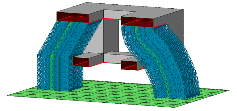
Avoiding part-to-part support with a knee (left) or a spline (right)
Jump to:
Working with the angle controls
An angled knee can produce part-to-platform and part-to-part connections.
To activate the angled knee
- Generate the volume or polyline supports.
- Select the supports to angle and choose
 Edit entity.
- Set Angled block support to Yes.
- Click OK and let the support regenerate.
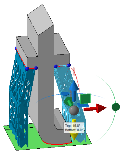
This spawns the angle control gizmo halfway along the overall support height, displaying the angles from the vertical for both sections, above and below the knee.
- The support's deflection above the knee you control by dragging the gizmo's cardinal axis arrows, planes, and center ball, simply by moving the point of the knee itself around in 3D. The maximum top angling is 70°.
- The support's deflection below the knee you control by dragging the gizmo's rotation arcs and the yellow arrow representing the effective deflection. The maximum bottom angling is 45°.
 Click on the textbox to open a dialog for numerical inputs of the deflection angles.
Note: Angles can only be changed numerically if a direction of angling already exists; otherwise, the direction is not defined and typing a non-zero angle number has no effect.
Click on the textbox to open a dialog for numerical inputs of the deflection angles.
Note: Angles can only be changed numerically if a direction of angling already exists; otherwise, the direction is not defined and typing a non-zero angle number has no effect.
Things to consider
- Change perspective often to verify the desired deflections in 3D.
- Moving the yellow deflection arrow is dependent on the view angle. This can produce confusing or unexpected results when viewed at any other direction than the cardinal ones. Instead, use the viewcube or the perspective switch to look at the scene straight from the front, left, top, and so on. This way, moving the arrow is exactly the same as using the rotation arcs which offer fine control and guaranteed rotation only along the associated axis.
- Switching Angled block support off and on maintains the last-set angling for as long as the associated supports exist and remain known to the support editor instance.
- In addition
deleting and regenerating the supports in question,
editing and typing 0 resets angling to zero, too.
Working with the spline controls
To activate the spline
- Generate the volume or polyline supports.
- Select the supports to angle and choose
Edit entity.
- Set Along a spline to Yes.
- Click OK and let the support regenerate.
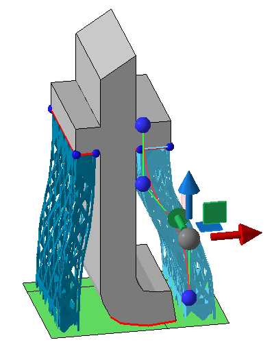
This draws the spline along the support, starting with four control anchors, or "basepoints".
Spline controls
- The top basepoints is always fixed to maintain the attachment location on the part surface.
- The bottom basepoints always moves across the platform surface.
- With the basepoints second from top or bottom, you control the last bend each before the actual connection.
- To move a basepoint, click on it and use the gizmo controls.
- To add a basepoint, hover the mouse pointer towards the centerpoint between two existing basepoints and click the transparent basepoint that is auto-generated as you approach the centerpoint.
- To delete a basepoint, right-click Delete basepoint from its context menu, if available.
- The four initial basepoints are fixed and cannot be deleted.
- Visibility of basepoints, the green basepoint line, and the red spline is toggled in its context menu.
Things to consider
- Spline-deflected supports ignore any geometry other than their own respective downskin cluster and do not generate dedicated connections to surfaces with which they intersect on the way down.
- The only way to truly reset spline deflection to zero is to delete and regenerate the supports in question.
 Repeatably apply externally generated spline coordinates