
Define skin regions and lattice kernel settings
We will use kernels in this model to thicken the lattice elements in regions requiring greater strength.
- Select Hollow - Region2, then press Ctrl+Left Mouse and select a few polygons on the flat front and back sides of the model.
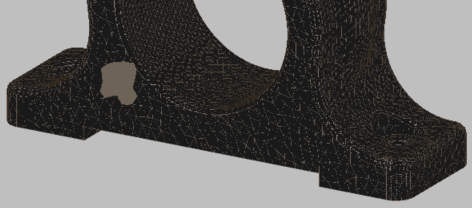
- In the Toolbar, Selection panel, set the
Tolerance value to
4, and if necessary, click
Flood Fill. The flat sides are filled.
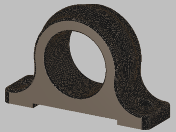
- Select Skin - Region1 and in the Selection panel, click
Select All. The curved surfaces and flat bottom are filled.
- In the
Properties Panel, expand
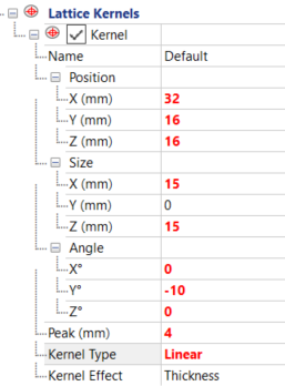
Lattice Kernels and the first kernel. Position the first lattice kernel in the lower, thick region of the part, between the large center hole and the side bolt hole. Try the following values, but you may need to modify them for the position of your model:
- Position (X,Y,Z): 32, 16, 16, to place the kernel in the center of the thick part.
- Size: 15, 0, 15, to define the dimensions of the box affected by the kernel. A zero Y value means that the box extends through the full Y dimension of the part.
- Angle: 0, -10, 0, to better align the kernel with the part shape.
- Peak: 4, to specify that beam thickness is incremented by 4 mm in the center of the kernel region.
- Kernel Type:
Linear
- Right-click .
- Right-click . A second kernel is created, with the same settings as the first one.
- In the second kernel, change Position X value to 82 mm, and Angle Y value to 10.
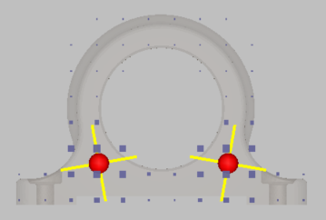
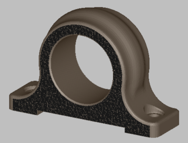
The result should be two kernels, positioned symmetrically inside the part lattice. To see both, click Lattice Kernels. Feel free to modify Position, Size, and Angle values if you wish.