
Commands available in the main menu and the context menu of support elements and anchors
 Some commands had their naming updated.
Jump to:
- Edit support
- Create
- Tips
- Anchors (main menu)
- Anchors (context menu)
- Cluster
- Density map commands
- Zoom to
- Close supporting
- View
Edit support
Commands for editing existing supports
 Select Select
|
Use this command to switch manually to using left-click to select supports, anchors, or clusters. Use the dropdown to switch how the selection of supports behaves:
Tip: When set to
Single supports, all connected supports are still selected at once by double-clicking one of the connected elements.
|
|
 Delete selection Delete selection
|
Deletes selected support elements and anchors. Default shortcut key: Delete |
|
 Edit support Edit support
|
Accesses the generation parameters, similar to the Edit tab in the context view, for selected supports. Modify them by either editing the property values directly or by applying a set of stored defaults. If multiple support entities are selected that have different parameters each, they show with "--" as the value, and changing them overrides and sets the new value for all selected entities. |
|
 Move support Move support
|
Shift the selected support entities along X and Y |
|
 Modify by polygon Modify by polygon
|
Shows a 2D projection of the area with the selected supports. Here you add, extend, or trim volume and polyline support by drawing shapes. (However, while bar supports do work as the "selector" for the area in question, they are not affected by this function.) Tip: The polyline to modify the active support is represented in both a 2D view snapin in the context view as well as the 3D view of the display and also respects the perspective of the 3D view.
|
|
 Reinforce polyline Reinforce polyline
|
If the selected entity is an open-ended polyline, this function duplicates it with a small offset on both sides of the original. Useful for strengthening single polyline supports along edges. |
Does not work with certain polylines, such as the cluster-following, enveloping polyline of volume support. |
 Split bar on anchors Split bar on anchors
|
Splits a bar into segments of independent bars at any anchors attached to it. Useful for working with bar bouquets, enabling a more granular adjustment of the individual sections between branches. |
|
 Delete unused anchors Delete unused anchors
|
Deletes anchors that are not connected to any support entities. Useful for cleaning up during manual support projection of bars, for example, or manual selection and deletion of only some of all support entities present. |
|
 Delete all anchors and entities Delete all anchors and entities
|
Does exactly that. Requires no selection. Use with caution as you are not asked for confirmation. |
|
 Upskin projection Upskin projection
|
Opens a snapin dialog in the context view for regenerating the selected bar supports to target a specified or detected upskin of the same part |
Create
Manually create new supports using the Manual defaults sets defined and selected on the Edit tab in the context view
 Create new bar Create new bar
|
The first click sets the first anchor. Only when the second anchor is placed, the bar is generated. Anchors can be placed in any order and constellation on the same part, on different parts, or the platform. Tips
|
|
 Create new polyline Create new polyline
|
Each subsequent click on the part extends the polyline support from the most recently placed anchor. To start a new polyline, click the button again. Tip: You may reuse existing anchors by clicking on them. That way you can close a polyline, for example. Note that you can still continue adding polyline sections by using other existing anchors or by placing new ones.
|
|
 Create new volume Create new volume
|
Left-click to place anchors at corner points along the circumference of the desired volume support. Note: Zig-zagging when you setting anchors unless should be avoided unless certain of
Netfabb's behavior. Otherwise, this may lead to unexpected support contours as
Netfabb connects anchors in the order of their placement and then fills only the enclosed area:
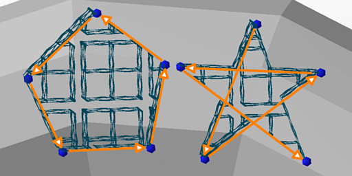 Left: a 5-point volume support, its contour defined by placing only nearest neighbors of anchors. Right: The same five points, but defined in a different order. |
 Settings
Anchors (main menu)
 Create anchor Create anchor
|
Switches to placing new anchors on part or platform surface with each click |
|
| Delete anchor
|
Switches to deleting anchors |
|
| Delete unused anchors
|
Removes any anchor that has no supports attached |
|
 Free anchor movement Free anchor movement
|
Frees the selected anchors from the default snapping to surfaces so that they can be moved in all directions |
|
 Export anchors Export anchors
|
Exports XYZ positions of currently present anchors to a semicolon-separated-list file |
|
 Import anchors Import anchors
|
Imports XYZ positions from a semicolon-separated-list file and creates anchors in those positions |
Anchors (context menu)
Right-click an anchor to access its context menu.
 Create bar Create bar
|
Adds a new bar on the selected anchor Uses the values stored in the set currently selected in |
Only active when Create new bar is active in the main menu. |
 Project anchor down Project anchor down
|
Adds a new anchor directly below the current one on the next available surface, part or platform alike |
Only creates the anchor; bar must be added separately. |
 Project anchor up Project anchor up
|
Adds a new anchor directly above the current one on the next available surface |
|
| Project anchor on platform
|
Adds a new anchor below the current one on the platform |
|
| Delete unused anchors
|
Removes any anchor that has no supports attached |
|
| Free anchor movement
|
Frees the selected anchors from the default snapping to surfaces so that they can be moved in all directions |
Only for anchors not already freed |
 Snap anchor to part Snap anchor to part
|
Disables free movement and attaches anchor to the nearest point on the part surface |
Only for freed anchors |
| Snap anchor to platform |
Disables free movement and attaches anchor to the nearest point on the build platform surface |
Only for freed anchors |
Cluster
 Mark cluster manually Mark cluster manually
|
Switches to selecting the definition of supportable clusters from the automatic detection using the Cluster detection options in the Analysis tab in the context view to a manual method. Select from the dropdown to change the manual selection mode.
For both the brush marking as well as the surface marking, as well as the critical and the noncritical angle, the Edge threshold parameter in the context view applies. |
|
 Call action on cluster Call action on cluster
|
Provides a list of available support scripts that contain actions which you can then run on a cluster. Also, the scripts are listed with their cluster-applicable actions only, and any actions not applicable to a cluster are omitted. Uses the chosen support action with the settings stored in the script,
|
|
|
Create bar support on cluster
|
Fills the cluster area with bar supports |
|
|
Create polyline support on cluster
|
Fills the cluster area with polyline supports |
|
|
Create volume support on cluster
|
Fills the cluster area with volume supports |
|
 Upskin projection Upskin projection
|
Switches context view to upskin projection controls to redirect where any supports present on the selected cluster should contact part surface or platform surface at their bottom end |
|
 2D mode of cluster 2D mode of cluster
|
Provides an additional bottom-up view of the part in a 2D editor for placing and manipulating supports |
|
 Export extruded cluster Export extruded cluster
|
Extrudes the selected cluster area into a mesh of specified thickness |
Density map commands
 Edit density map/ Edit density map/ Free density map editor Free density map editor
|
Adjust spherical locations within the space occupied by the part and its support |
|
| Projected Density Map Editor
|
Affects a cylindrical volume and adjusts in height as it intersects with the supported surface and the bottom end of the support, be that the platform or another part surface. |
|
|
Surface Density Map Editor
|
Use brush controls to freely specify areas on the part surface that, projected towards the platform, determine where the density map should be changed. For this, the context view provides input controls to specify the size of the brush, the factor to be applied, and the behavior for applying factors multiple times. |
Zoom to
Zoom and focus commands
 Zoom to part Zoom to part
|
Centers and magnifies view on the part |
|
 Zoom to selected Zoom to selected
|
Centers and magnifies view on the current selection of supports |
|
 Zoom to area Zoom to area
|
Requests to drag a rectangular frame, then centers and magnifies view on the framed area |
Close supporting
Commands to close the support editor
| Apply to part |
Attach the generated supports to the part and return to the main platform view. |
|
| Apply to all part copies |
If compatible, the support generated on one part is applied to all of its clones. |
Important: Compatible parts are those that are immediate clones of each other, including the original one, as long as they are not mesh-modified (repaired, textured, …) and are not moved in Z, and are not scaled or rotated.
|
| Close supporting |
Aborts support editing and closes the support editor, unloading it from the project tree |
View
The
View category in the main menu contains commands to control visualization in the support editor in addition to or replacement of the regular View commands.
| Perspective |
Holds seven default perspectives to move and orient the camera in the 3D view |
|
| Zoom to |
Zoom to and focus on the part, a selection (like a selected cluster or support element), or an area. |
Equivalent to Zoom to |
| Highlight triangles |
Highlights the individual triangles by their edges |
|
| Show edges |
Highlights supportable edges with a red line |
|
| Show part |
Enables or disables rendering the part, leaving any supports still visible for inspection |
|
| Transparent part |
Renders the part mesh transparent, leaving supports still visible without completely hiding the part mesh |
|
| Show support |
Enables or disables rendering support elements |
|
| Transparent entities |
Renders supports transparent |
|
| Show anchor |
Enables or disables the blue anchor spheres |
|
| Show platform |
Enables or disables the green platform area |
|
| Hide non-selection |
Supports that are not selected are hidden. Select supports by clicking on entries in the List tab of the context view. |
|
| Hide support at platform |
Any supports not in contact with the buildroom bottom surface are forcibly set to invisible. |
|
| Zoom to selection |
Enables or disables automatic zoom and focus on a new selection |
|
| Set clip plane for selection |
Enables or disables an automatic repositioning of the Z clipping plane whenever an entry in the List tab (not the 3D view) is clicked |