
Controls, options, and settings on the context view tabs explained
The
context view holds most of the controls to work with supports. Additionally, the
 Settings hold switches for less often used parameters.
Jump to:
- Context view tabs overview
- Context view: Analyze
- Context view: Edit
- Context view: List
- Context view: Support scripts
- Context view: Process simulation
- Settings
Context view tabs overview
| Analysis |
Cluster detection controls how the downskins, made up of triangle clusters, are detected for viewing and for manual support generation. Mark cluster manually holds the settings for manually selecting triangles to be supportable clusters |
| Edit |
Edit the generation settings for the currently selected support elements here, either by adjusting values directly or applying a set. Use Sets to manage custom values for supports. Sets are also looked up whenever you place supports manually. |
| List |
Any available support elements are listed here, grouped by the clusters they belong to.
|
| Support scripts |
Support scripts are at the heart of Netfabb's support generation. They consist of support actions with already defined values. On this tab, scripts are edited, and saved and loaded for later use, even exported and imported. |
| Process simulation |
Contains visibility and visualization settings for the display of simulation results These print simulation results are generated by using a metal powderbed machine workspace based on material and toolpath selection and sending the generated solution to Autodesk® Simulation Utility for Netfabb® (included in the Ultimate subscription) or Autodesk® Netfabb® Local Simulation as included in the separate product Autodesk® Netfabb® Local Simulation. Also contains controls to perform optimization on any bar lattice support |
 Click the visibility icon to hide or show individual support elements.
Context view: Analyze
| Analyze | ||
|---|---|---|
| Critical angle |
Triangles tilted up to this angle from the horizontal are considered to require support. Use this visual aid at your discretion to find surfaces which must receive supports. Triangles so detected are highlighted in dark red. |
|
| Non-critical angle |
Triangles tilted up to this angle from the horizontal receive support if they are adjacent to enough other triangles that also require supports. This generates a smoother cluster silhouette. A smoother support silhouette makes removing supports easier. Triangles so detected are highlighted in yellow. The resulting cluster is highlighted with a bright red outline. |
|
| Minimum area |
Detected areas that would receive supports but are smaller in size than this threshold do not get supported. |
|
| Respect face groups |
If a cluster spans a single face group only partly, or spans multiple face groups, every section thus created is treated as if it were a separate cluster. |
Enabled only when the part actually has face groups. |
| Detection mode |
Cluster and edge detection can be quite resource-intensive for highly intricate parts, or may not even be required at all if you fully rely on the detection within scripts. Switch here between the fastest None, the very fast Downskin visualization, and the regular but (on very highly detailed mesh) potentially costly Cluster detection to fit your workflow and part complexity.
|
Note: Only with
Cluster detection enabled can detected clusters be interacted with, such as with commands like
 Call action on cluster. Call action on cluster.
|
| Analyze automatically |
For very complex meshes with many triangles, the cluster detection can take some time. To avoid binding up system resources for recalculation every time a setting is changed, you can turn this off and perform the new analysis on demand using the button Analyze downskins. |
|
| Brush size |
Adjusts the brush size for when
|
Note: Manual marking and automatic detection cannot be combined. Also, the critical and non-critical angle for manual marking is fixed at 90°.
|
| Edge threshold |
When manually marking clusters, triangles under the brush but beyond a convex edge remain unmarked when its angle is sharper than this threshold. Also applies to flood-filling of surface patches. 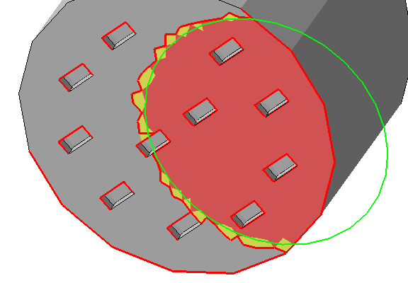 The edge threshold makes marking large areas with many small perforations much easier. |
|
| Show environment |
Toggles visibility of other parts partly or fully above or beneath the current part. |
|
| Recalculate |
If you changed the arrangement of parts outside the support editor, use this button when you return to test and adjust for changes in parts overlapping each other. If such parts are detected, Show environment is forcibly switched on. |
|
| Anchor diameter |
Adjusts the size of the dots that highlight control and attachment points of supports on part surface and other places |
|
| Support volume with <value><unit> laser size |
Uses a value defined in the
|
Caution: For performance reasons, this is only a rough estimate based on surface and thickness and
ignores any enclosed volume.
|
 Mark cluster manually
Context view: Edit
| Edit | ||
|---|---|---|
| Manual defaults dropdown |
Lists the three built-in sets of support generation values as well as any custom sets This selection is also used for the manual placement of new supports through the commands in the Create panel of the Support menu category.
|
There is currently no way to see the parameter values stored in a set; only their results can be seen by applying the set to support elements present on the mesh. |
 (New value set) (New value set)
|
Prompts for a name of a new set and generates one |
|
| (More actions)
|
Holds further commands
|
Rename value set is disabled for the built-in sets |
 (Delete) (Delete)
|
Deletes the current value set |
|
| (parameter listing) |
Lists parameters for selected supports of a type. If selected support elements have different values for a parameter between them, the value shows up as --. Typing and confirming with Enter immediately adjusts the generated support elements to match the change. |
|
| Save as defaults |
Saves the generation values of the selected support geometry to the currently selected set |
For non-built-in sets only |
| Apply defaults |
Applies the applicable values from the set of defaults currently selected in the Manual defaults dropdown to the support elements currently selected |
Permits selection of multiple different support types at once |
 Save as defaults and
Apply defaults were previously located behind the
(More actions) button but are now below the parameter listing for better visibility.
Save as defaults and
Apply defaults were previously located behind the
(More actions) button but are now below the parameter listing for better visibility.
Context view: List
| List | ||
|---|---|---|
| (support element listing) |
Any available support elements are listed here, grouped by the clusters they belong to.
|
Individual visibility is overridden by some switches in the View category of the main menu. |
| Replay support actions |
Reruns any script-based support generation previously executed on the current mesh, effectively reverting any manual edits to generated supports performed since the last run, such as adjustment of anchors but leaving elements from other, separate generation methods such as manual placement intact |
Context view: Support scripts
| Support scripts | ||
|---|---|---|
| (Support script dropdown) |
Select the support script to use |
The example scripts that come with Netfabb cannot be edited. However, you can copy them and edit the copies. |
| (New script)
|
Create a new script from scratch |
|
| (More actions)
|
Rename, duplicate, or export the current script or import from file, or create or import and apply a table of value parametrization to generate series of meshes with individualized support parameters |
Rename and Execute parametrized script disabled for the built-in scripts |
| (Delete script)
|
Deletes currently selected script |
Disabled for the built-in scripts |
| (Script listing) |
Access individual actions of the script |
|
| (Action dropdown) |
Select the support action to add |
|
| Add |
Adds the selected support action to the bottom of the current script |
|
| Save |
Saves any changes made to the current listing to the script |
|
| Execute |
Deletes all current downskin definitions, anchors, and support elements and runs the script with its current values. |
Caution: Does not ask for confirmation. To enable a confirmation prompt, switch
Settings > Settings > Supports > Ask on deletion of all support to
Yes.
|
Context view: Process simulation
| Process simulation | ||
|---|---|---|
| Show process simulation, Show simulated part, Show simulated plate, Show simulated supports, Opacity, Displacement scale |
These switches and sliders control the visualization of simulation results. |
|
| Generate density map |
Uses von Mises stress data from simulation results to adjust density map values. Provides a curve editor that maps density factor against fraction of a specifiable stress value. |
|
| Optimize support lattice |
Adjusts thickness of bars generated with the Adaptive lattice bars support action based on stress simulation |
|
| Optimization settings |
Provides access to the simulation and optimization settings for lattice bar support optimization |
|
| (Bar stress histogram) |
Displays count of bars by stress value in increasing order. Clicking the bins selects the respective support elements. |
Uses 25 bins |
Settings
These are located at
Settings > Settings > Supports.
| Colors |
Sets the colors used for things like the platform, mesh, supports, anchors, and down-oriented edges |
| Decimal digits |
Adjust this to have the required number of decimal places displayed. |
| Zoom animation duration |
To help with recognizing the orientation of a part after a switch of perspective, the transition to the new perspective is animated. Use this to affect the speed at which the animation runs. |
| Show cutplanes |
When using the clipping planes, or cutting planes, this switch toggles visible, semi-transparent planes at the cuts. When off, only the contours along the clip or cut are highlighted. |
| Zoom orientation |
When switching through support entities in the List tab while Zoom to selection is active, this perspective is used when focusing on the respective support entity. |
| Mouse action for bar support |
For the command
|
|
Ask on deletion of all support |
Toggles whether to ask for confirmation upon choosing to delete any and all existing supports |
| Laser diameter for volume calculation |
For calculating the amount of material rendered for non-solid supports, this diameter is used as the width of a single-pass toolpath. |
| Apply as part attachment |
Set this to No when you do not want to create supports as attachment but rather as separate part. Some older applications and formats need this as they do not recognize dedicated support structures. For example, attached support is dropped when exporting meshes to STL instead of the modern 3MF. Note: You can always convert support structures regardless how you generated them using the
Manage support command in the
Home toolbar, but keep in mind that attaching a mesh that was parametric previously does not restore the parameters how it was generated, so you cannot edit them in the support editor.
Caution: The meshes so generated can be, and often are, unsuitable for printing as regular parts where support-specific toolpathing would otherwise accept the technically flawed mesh just fine. Make sure that either you process the support meshes appropriately yourself or that they are inherently treated as supports by your workflow anyway.
|
| Respect part environment |
When set to No, the support editor ignores any part other than the one you are currently working on in the support editor even when it would intersect with projected supports of the current part. This also includes no-build zones. 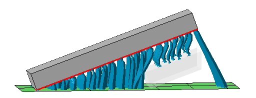 Two separate blocks in the build room. One is being worked on in the support editor, the other one (displayed with transparency) is acknowledged by the editor. Note how only a section of the other part is taken into account even though it is actually a full copy of the first (not shown). This is done for performance reasons but may lead to unexpected results like the bar supports to the platform on the far right. |
| Environment size |
Sets the extra space around a part to be checked for other parts. Increase this if you often work with widespread parts closely nested against each other. |
| Use voxel grid for walls |
Supports near walls can interfere with the same walls. When using the voxel grid approach, the wall detection is improved but the calculation cost increases. |
| Voxel grid size, Voxel grid height |
The size of the voxels affects accuracy of wall detection and avoidance but incurs proportional computation costs. |
| Show Apply behavior dialog |
When applying support from the support editor, you are asked with a dialog whether to keep or terminate the support editor entry in the project tree. The dialog contains a checkbox to choose to always use this dialog. After unchecking the box, your last choice is remembered and the dialog no longer appears. With this option, you get the dialog to appear again. |
| Remove old support before script execution |
Typically, a support script is there to generate all required support at once, invalidating and possibly even negatively interfering with existing supports. As such, Netfabb deletes any existing support by default before running the script. Setting this switch to No disables the deletion. |
| Projection height, Fixed height |
In some additive processes, parts do not require supports to reach all the way to the platform and be anchored there, they just need a flat base to stand on once released from powder or substrate. This setting effectively simulates a fixed distance of the part to the platform for supporting purposes regardless at what Z height in the buildroom the part actually sits. Switch Projection height from On to platform to Fixed height to enable this function, and use the parameter Fixed height to specify this simulated fixed distance. |
 Create new bar