
Determine straightness for lines through multiple points. Measure an offset for a line. Choose an alternate angle.
How PowerInspect measures for lines depends on the measurement type.
Measure the straightness of a line defined by multiple points
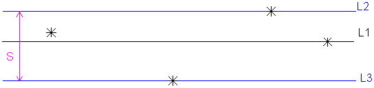
When you use more than three probed points to probe a straight line, PowerInspect creates a best fit line (L1). This line minimizes the deviations of all the points. PowerInspect then creates parallel lines (L2 and L3) through the furthest points in the positive and negative directions.
The distance between L2 and L3 (S) is the straightness of the line. If this distance is greater than the maximum that you specify, the straightness is out-of-tolerance.
When you specify more than two points to create an offset line, PowerInspect calculates a best-fit line that minimizes the deviation of all the points. You can specify the maximum acceptable deviation between the points and the line. If any point exceeds this maximum, PowerInspect reports that the straightness of the line is out-of-tolerance.
Use probed or reference points for an offset
If you use probed or reversed probed points as the offset type, you must probe the points to create the offset line. If you use only reference points as the offset type, PowerInspect creates the line from the specified points.
The Material Condition setting deternines where PowerInspect creates the line:
- Mean. Creates a line or plane running through the average height of the probed points. For example:
 Reference plane
 Probed points
 New feature
-
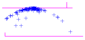
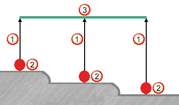
Maximum Material Condition. Creates a line or plane running through the point furthest from the reference item. This positions the item at the highest point of a boss.
-
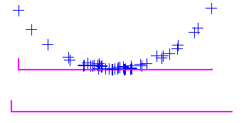
Least Material Condition. Creates a line or plane running through the point nearest to the reference item. This positions the item at the lowest point of a hole.
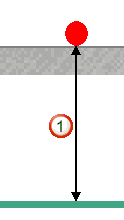
Measure an offset from a point
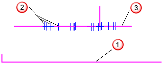
The Offset Line item constructs a line from points on different surfaces of a part. For example, this illustration shows how applying different offsets
to the probe points
produces an offset line
.
PowerInspect calculates offsets for probed points and reverse probed points from the theoretical contact point. For probed points, Offset Value
= Apparent Offset - Probe Radius. For example:
For reversed probe points, Offset Value
= Apparent Offset + Probe Radius. For example:

Measure an alternate solution for an angle
When only two points define an offset line, PowerInspect calculates two solutions. This illustration shows two lines offset from the same two points:
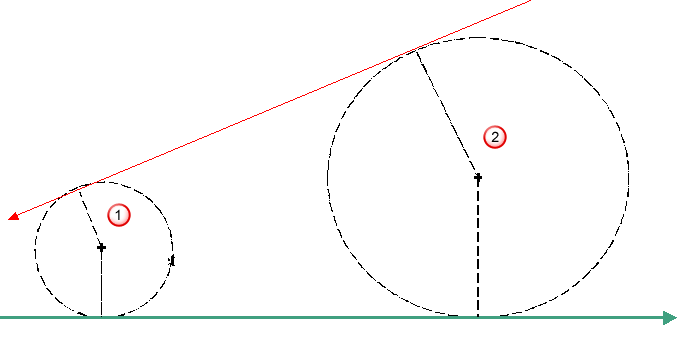
3 mm offset for Point 1
5 mm offset for Point 2
In the Offset Line dialog, select the Select The Alternative Solution option to use the alternate solution to what PowerInspect chooses.