
Use the Form tab > Points panel > Import > options to create an inspection group by importing a set of nominal point coordinates from a text file, or a curve from a .ddx, .ddz, or .dgk file.
To import points from file:
- Click Form tab > Points panel > Import, and choose an option to specify which type of group you want to create. Select:
- Create Surface Inspection Group to import the points into a new surface points group.
- Create Edge Inspection Group to import the points into a new guided edge points group.
- Create CNC Surface Group to import the points into a new CNC surface points group. If probe path generation is disabled, this option creates a guided surface points group.
- Create CNC Edge Group to import the points into a new CNC edge points group. If probe path generation is disabled, this option creates a guided edge points group.
The import options that are available depend on the type of machine you are creating the inspection for.
- In the Import Points Wizard, click Browse.
- In the Open dialog, select the file that contains the points you want to import, and click Open.
- If PowerInspect recognizes the file extension, it displays descriptions of the file types in the Possible Formats tab. Select the format of the data.
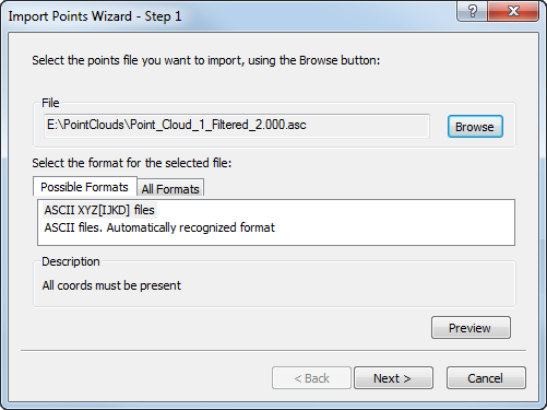
If no format is displayed, click the All Formats tab and select the format from the list.
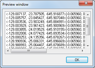
- If you want to check the format, click Preview to display the coordinates in the file. The Preview window is displayed. Click OK to close the window.
- Click Next. A summary of the import options is displayed.
- Click Next to create a group in the inspection sequence and import the points.
- When the import is complete, the points are displayed in the CAD view, and a message reports the number of points imported. Click OK to close the message, and then click Finish to close the wizard.
- If you are importing edge points, check and edit the Probing settings in the Features tab, then click
 to save the group.
When you import points that have an orientation, their orientations are preserved. When you import geometric points without an orientation, their treatment depends on whether you have a CAD model:
- Without a model, the orientation defaults to the positive Z direction.
- With a model, the point uses the normal of the nearest surface within the Proximity criteria distance specified in the Measure Parameters dialog. When no surface is within range, the orientation defaults to the positive Z direction.
Example of comma-separated coordinates in XYZIJK format:
106.451827,50.000006,34.095465,-0.290788,-0.541083,0.789096
-0.000002, 49.524182,15.847267,0,-0.541082,0.84097
-80.268954,50.093428,25.603407,0.219156,-0.541084,0.811911
-97.762263, 0,15.50753,0.303025,0,0.952983
0,0,-0.600686,0,0,1
76.53957,0,9.198199,-0.23697,0,0.971517
91.946816,-50.000014,29.156563,0.251169,0.541084,0.802585
-1.627348,-50.000014,15.112013,0.004443, 0.541082,0.840958
-94.703469,-50.000002,30.033494,0.258701,0.541083,0.800189