
Adding the Pile and Diaphragm Sub Models
The next step is to define the pile and diaphragm sub models which can be achieved by creating a 2D sub-model in the vertical plane along the east abutment. This can then be copied to the west abutment.
(If not continuing from last section, open "EU Example 10_2 Composite_Beam.sst" via Help | Tutorials | Open Tutorial Model... from the main menu.)
In the Structure Definition navigation window toolbar click on the
 button to select 2D Sub Model and click on the YZ button then click ✓ OK.
Click on “Sub Model Members” in the 2D Sub Model: 2D Model A object to open the Define Sub Model Members form.
Click on the Single Member draw mode toolbar button (
 ) and click on the bottom left hand node on the beam web.
Click on the Draw to a specific position or offset toolbar button (
 ) then click on the Offset value button.
Enter a v offset of “-4m”.
Repeat the process to define the other pile.
Click on Split Beam Element from the list of Member Tasks then click on the by specified divisions button, set the number of new elements to 8, then click on the “Apply” button.
Click on the first pile and click on the “Apply” button again, then close both the forms.
Click on 2D Sub Model: 2D Model A in the navigation window then click on the
 to select “Mesh” from the drop down list.
Set the Member type to “Finite Elements”, the Transverse Number to “2” and the Longitudinal Number to “4”.
Set Pick to “by point”.
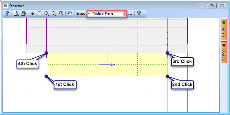
On the graphics window put the mouse on the General tab and tick the Show Nodes option. The nodes will show up as blue dots.
Set the Snap mode to “Node in Plane” and click on the 4 nodes highlighted in the screenshot below, starting with the bottom left then bottom right, top right and top left. This will create a finite element mesh.
Change the Name to “Diaphragm” and close the Define Sub-Model Members form with ✓ OK and clicking “Yes” on the confirm form.
In the Structure Properties navigation window click on the
button and select Design Section to open the _Structure Properties: Section _data form.Select a Section Reference of “H Pile”, and set the Section Reference Axis Relative to: to “Origin”; then window round the whole structure. This will try to apply this section to all beams in the structure, so select “No to All” when asked if beams already assigned should be overwritten. This will ensure that only the pile members will be assigned.
Close the form with ✓ OK.
Click on the
toolbar button again and select Finite Element from the dropdown list.Set Thickness to “500mm” and then select the 8 finite elements in the diaphragm.
Change Description to “Diaphragm" and close the forms.
In the Structure Definition navigation window use the
button to add Supported Nodes.Change the Select field on the graphics toolbar to “All Joints” and click on the two bottom nodes of the piles.
Fix the joints in all six directions then click ✓ OK to close the form.
The next step is to copy the sub model to the other end of the structure. Right click on 2D Sub Model: 2D Model A and select “Copy” from the popup menu.
Click on the Define button and set X to be “30m”, leaving Y and Z at their current values.
Click on the “Next” button 3 times on the Define Plane form and then the ✓ OK button.
Click on the “Next” button on the Copy Sub Model form to copy the sub model. A summary of the new members, elements, joints and supports created is then displayed.
Click on ✓ OK to close the Copy Sub Model form.
Click on the Show advanced model view icon (
 ) to view the elements of the structure in a 3D representation. Clicking on the Object Browser tab below the Navigation Pane and selecting an element in the graphics window displays detailed information about that element in the space that is normally occupied by the Navigation Pane. Note that unless the Filter is set to “Select all” then not all of the members will be rendered in the 3D representation.
Save the file as “My EU Example 10_2 Full_Structure.sst”.