
Creating the Curved Slab
The next step is to alter the z coordinates of the slab nodes to represent the curved profile. To do this the 2D sub model needs converting to a 3D sub model (losing all details of the mesh).
(If not continuing from last section, open "EU Example 10_2 Slab.sst" via Help | Tutorials | Open Tutorial Model... from the main menu.)
- This is done by clicking on the sub model in the navigation window and, by using the right mouse button, choosing the menu option Convert to 3D sub model.
- Confirm the conversion when asked.
- Open up the Joint Details form by clicking on this item in the Navigation Pane and ensure the view direction is a plan view.
- Draw a selection window round the left most transverse row of joints to select them. These joints will be displayed as red.
- Hold the “Ctrl” key down and draw a selection window round the right most transverse row of joints to add these to the selection set.
- Click on the Edit... joint task to display a secondary form to allow editing of the coordinates.
- Choose the Specific value option and enter “-1.000” in the Z field before clicking on the “Apply” button.
- Without closing the Edit Joint Coordinates data form, select the second column of joints from each end in the same way as before, and change the z coordinate to “-0.810” before clicking the “Apply” button.
- Repeat this with appropriate Z values (given in the table) for the other columns of joints.
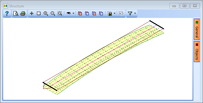
- Close the Edit Joint Coordinates form and use the graphic toolbar button to set the view as isometric.
- Close the Joint Details form in the normal way.
| Row of joint | Z Coord (m) |
|---|---|
| 1 | -1.000 |
| 2 | -0.810 |
| 3 | -0.640 |
| 4 | -0.490 |
| 5 | -0.360 |
| 6 | -0.250 |
| 7 | -0.160 |
| 8 | -0.090 |
| 9 | -0.040 |
| 10 | 0.000 |
| 11 | 0.000 |
Before moving away from the curved slab geometry it is worth checking the local axis directions of the finite elements and beams as the rules for elements not in a global plane are different to those that are.
- Click on the General button on the right side of the graphics window and tick the Local Axis box. Some of the finite elements may have different direction to the others, depending on the order in which they were generated, and to ensure that any propertied assigned and results output are sensible then it is necessary to make them consistent.
- In the Structure Definition navigation window, first click on the Refined Model node and then use
 to add an Advanced FE set | Local Axes which will open the Specify FE Local Axes Set form.
 - Type should be set to “by Plane” and Orientate Element w.r.t. set to “Plane XY”.
- Window round the entire slab in the graphics window to apply this to all the finite elements and then in the Confirm form select “Yes to All” and then close the data form with ✓ OK.
The deck slab geometry is now complete so a design line, carriageway and span end lines can be added to the structure definition. The local axes display can now be turned off if required.
In the navigation window click on the Refined Model node and use the
toolbar button and select Design Line to open the Define Design line form. The structure will be displayed in an xy view.Click on the middle node at the left hand edge of the structure, then on the middle joint at the right hand edge of the slab to create a design line “DL1”.
Click on ✓ OK to close the Define Design Line form.
To create the carriageway use the
button (when the Refined Model node is highlighted) and select Carriageway.In the Define Carriageway form set the design line to “DL1” and change the offsets to +/- 1.9m on either side of the design line for both footway and carriageway as follows:
- first footway/verge offset A = -1.9, offset B = -1.9 (zero width)
- primary carriageway offset A = -1.9, offset B = 1.9 (3.8m wide)
- second footway/verge offset A = 1.9, offset B = 1.9 (zero width)
Click on ✓ OK to close the Carriageway form.
The two span end lines are added in a similar way and are best created by opening the Span End Lines form, inserting two rows in the table and entering the four coordinates manually (0,0) (0,4) (30,0) (30,4).
Click on ✓ OK when the span end lines have been defined.
Close the data forms in the normal way and save the data file as “My EU Example 10_2 Curved_Slab.sst”.