
Beam Definition
Only one girder needs to be defined (the north one) as it can be mirrored for the south girder.
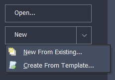
Start the program and select the New drop down button item Create From Template and pick the “EU Steel Composite” template to create a new beam.
Use the main menu File | Titles to set a title for the beam as “Composite banana beam” with a sub title of “Example 10.2”, a Job Number of “10.2” and add your initials in the Calculations by: field before closing with ✓ OK.
In the Materials navigation window, delete the concrete material C40/50 and the prestress material Grade 1637 by selecting them, one by one, and using the navigation toolbar button
 , which will leave three materials.
Open the structural steel S355/355 material and change the Yield Strength to “345” to make it S355/345 before closing the form with ✓ OK.
Define a second structural steel material S355/335.
In the Design Beam navigation window select the item Beam Definition to open the Define Composite Beam form.
Set the MAIN SPAN to be “Continuous-internal span” with a span of 30m and the SIDE SPANS as “End spans” with spans of 4.0m (accept the warning message about spans being outside expected range).
Set the Cross section to “uniform” and the Location as “Inner beam”.
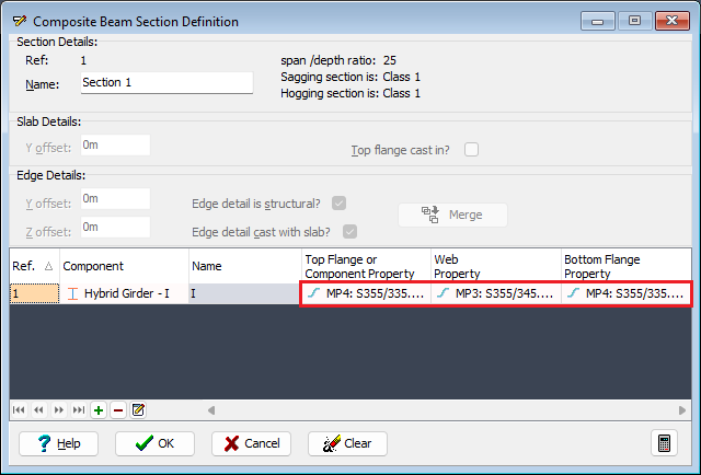
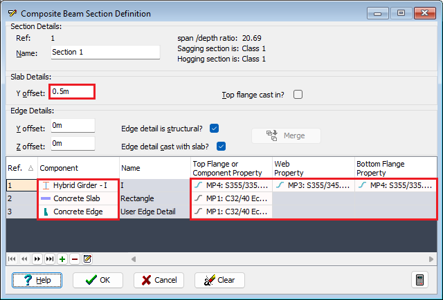
In the Define field select “Section” to open the Composite Beam Section Definition form.
Create a “Hybrid Girder - I” component with “500mm” wide flanges and a “1000mm” depth overall. The thickness of flange and web are “50mm” and “28mm” respectively.
Close the Component form using the ✓ OK button.
Click in the Property field for this component which allows different grades of steel to be assigned to each plate component.
Assign "MP3: S355/345" to the web and "MP4: S355/335" to both flanges.
Create a second component as a “Concrete Slab” setting the slab Width to be 2000mm and the Depth to be 200mm.
Close the component form using the ✓ OK button.
In the Slab Details set the Y offset to be 0.5m.
Now add a third component as “Concrete Edge” and create 5 coordinate points by using the + button at the bottom of the form and entering the data as shown below:
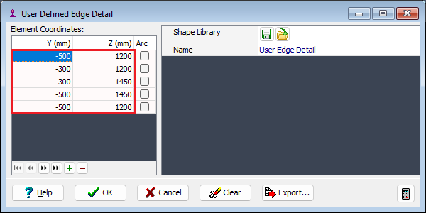
Close the User Defined Edge Detail form with the ✓ OK button and ensure the material properties are assigned correctly (grade C32/40 concrete) and that the edge detail is structural and it is cast with the slab.
Close the Section Definition form, then note and click Yes on the confirm form.
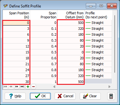
Open the Define soffit profile form using the appropriate option in the Define field.
Enter the profile points into the table as shown below:
| Proportion of span | Offset (mm) |
|---|---|
| 0.0 | 500 |
| 0.1 | 320 |
| 0.2 | 180 |
| 0.3 | 80 |
| 0.4 | 20 |
| 0.5 | 0 |
| 0.6 | 20 |
| 0.7 | 80 |
| 0.8 | 180 |
| 0.9 | 320 |
| 1.0 | 500 |
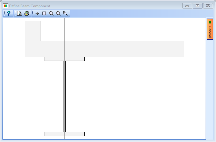
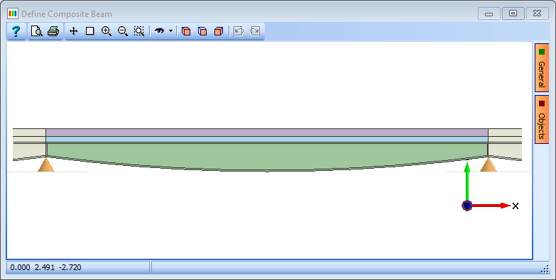
The general beam has now been defined – lateral restraints, web stiffeners and shear connecters may be added in the design stage.
- Close all the open forms (using the ✓ OK button) and save the file as “My EU Example 10_2 Banana_Beam.sam” using the File | Save as menu option.