
Assigning the Composite Beam
(If not continuing from last section, open "EU Example 10_2 Curved_Slab.sst" via Help | Tutorials | Open Tutorial Model... from the main menu.)
In the Structure Definition navigation window click on the
 button and select FE Web from the list. To allow cracked concrete properties to be assumed in the end hogging regions of the slab, the field Proportion from left/right can be entered at “0.06” (i.e. just over one element).
Set Name to “North Girder”, change to a plan view and click on the bottom edge of one of the top row elements.
Accept the two information messages.
Click on the Add Additional FE Web... button (accepting the information message about aspect ratios) and tick the Mirror Design Beam button.
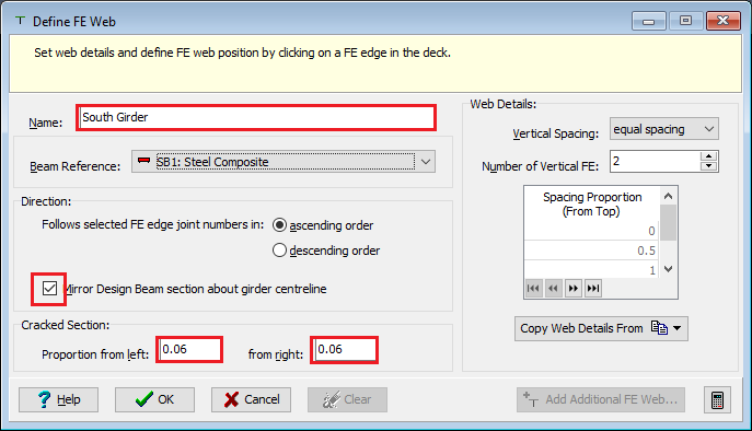
Set Name: to “South Girder” and click on the top edge of one of the bottom row elements and accept the information message, then close the form.
Click ✓ OK on the Define FE Web form and accept the information message about aspect ratios.
There should be no changes to be made but, it is worth inspecting the section properties that have been created in the process of assigning FE Web members by using the Structure Properties navigation window.
In the Structure Properties navigation window click on the
button and select Design Section to open the Structure Properties: Section data form.Select a Section Reference of “Edge Upstand”, the Section Reference Axis Relative to to “Origin” and then window round both the north and south edge of the structure before closing the form with ✓ OK.
Use the main menu File | 3D Elements View to view a 3D representation of the structure as it stands.
It should be noted that the upstand on the south edge of the structure is not situated correctly in a lateral position. To rectify this, a longitudinal beam (string of beam elements) can be created for this edge and then reversed.
In the Structure Definition navigation window select Longitudinal Beams to open the Longitudinal Beams form.
Window round the south edge beam, to create a longitudinal beam between span end lines, and then in the Beam Tasks click on Reverse Order to change the direction of the local axes of these beams. Now the 3D elements view will show the corrected location of the edge beams.
The next step is to modify the virtual members, created when the FE webs were defined, to include the upstand edge beam members. To do this, go to the Calculate | Define Virtual Member menu item.
Change to a plan view and make sure the pick mode is set to “Beam Element”.
Select “_FE Web A_” and draw a box around the top edge of the slab.
Repeat the process for “_FE Web B_”, selecting the bottom edge.
Rename “_FE Web A_” and “_FE Web B_” to “North Girder” and “South Girder” respectively, by selecting and overtyping.
Then close the Define Virtual Member form with ✓ OK and save the data file as "My EU Example 10_2 Composite_Beam.sst"