
Transfer Analysis Results to Design Beam
(If not continuing from last section, open "EU Example 10_2 Dead_SDL_Influence.sst" via Help | Tutorials | Open Tutorial Model... from the main menu.)
The next step is to transfer the results of the analysis to the appropriate design beam which can be done by selecting the Calculate | Transfer Results menu item. This will open the Transfer Results form.
Set the Transfer Type field to “Virtual Member”.
Click on the graphics window anywhere along the reference axis of the south girder to highlight the virtual member that will be used to determine what results will be transferred to the design beam tables.
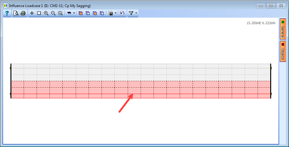
The selected beam will be highlighted and its details shown in the Transfer Results form. Alternatively “South Girder” can be selected from the Virtual Member field.
Click on the + button at the bottom of the table to create six blank rows of data. The Method field should be set to “(1) Smoothed” for this example.
Click in the first row of the Design | Load Case column and select “Construction stage 1”.
Click in the Type column and select “Compilation”.
Click in the Structural Analysis | Load Case column and select “C1: DL ULS”.
Repeat the process in the second row, this time setting Structural Analysis | Load Case to “C2: DL SLS”.
In the third row set Design | Load Case “Surfacing 1”, Type to “Compilation” and Structural Analysis | Load Case to “C3: SDL ULS”.
Repeat the process in the fourth row, this time setting Structural Analysis | Load Case to “C4: SDL SLS”.
In the fifth row, set Design | Load Case to “Traffic gr1b-gr5 +ve Moment 1”, Type to “Compilation” and Structural Analysis | Load Case to “C5: VM2-11; My Sagging; GR5 ULS STR/GEO”.
Repeat the process in the sixth row, this time setting Structural Analysis | Load Case to “C6: VM2-11; My Sagging; GR5 SLS Characteristic”.
The table in the Transfer Results form will now look like this:
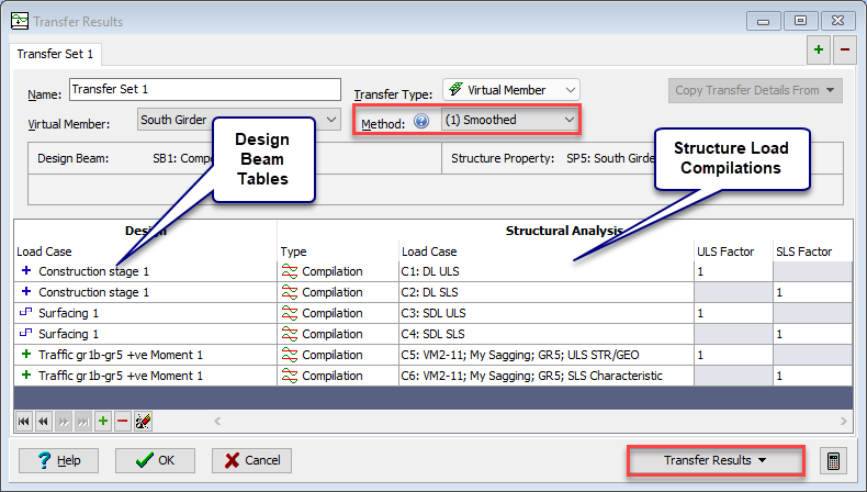
The Current Set can now be transferred to the EU steel composite design beam by using the Transfer Results button.
The composite Design Beam can then be checked that the beam has sufficient resistance under all loads in a similar way to the procedures defined in example 5.1.
When all design checks have been completed the project file can be saved to a file named “My EU Example 10_2 Complete.sst” before closing the software.